
Current limiting system and current limiting method for fuel cells

a current limit and fuel cell technology, applied in electrochemical generators, process and machine control, instruments, etc., can solve the problems of increasing the number of fuel cell stacks. the effect of limiting the number of fuel cell stacks

Active Publication Date: 2005-06-30
HONDA MOTOR CO LTD
View PDF1 Cites 5 Cited by
  • Summary
  • Abstract
  • Description
  • Claims
  • Application Information

AI Technical Summary

Benefits of technology

The present invention provides a current limiting system and method for fuel cells that can limit the electric current generated by a fuel cell stack. This system and method can detect the voltage and current of each cell in the fuel cell stack and set a target current limit value based on the detected voltage. The system can also gradually change the current limit value based on the generated current value of the fuel cell stack. This can prevent abrupt output changes and contribute to a stable electricity-generation control for the fuel cell stack. The technical effects of this invention include the ability to limit the electric current generated by a fuel cell stack, prevent abrupt output changes, and contribute to a stable electricity-generation control for the fuel cell stack.

Problems solved by technology

In the case where the temperature of the fuel cell stack is lower than a predetermined temperature at the time of operation of the fuel cell stack, or in the case where the solid polymer electrolyte membrane is not sufficiently humidified to a predetermined humidified state and the ion conductivity has been deteriorated, the electricity generating efficiency deteriorates and the cell voltage of each single cell often lowers accordingly.
While the cell voltage has been lowering, if generated electric current is taken out as much as in the case of the normal state where a decrease in cell voltage has not been occurred, the fuel cell stack becomes unstable, resulting a further decrease in the cell voltage or a deterioration of the solid polymer electrolyte membrane which ends in deteriorated durability of the fuel cell stack.
However, in this technique, notwithstanding the amount of generated electricity taken out from the fuel cell stack, the current control is carried out by changing the current limit value as soon as the lowest cell voltage varies.
Such unnecessary operations often make the control of the fuel cell stack unstable.

Method used


Image

  • Current limiting system and current limiting method for fuel cells
  • Current limiting system and current limiting method for fuel cells
  • Current limiting system and current limiting method for fuel cells

Examples


Embodiment Construction

[0024] With reference to the accompanying drawings, an embodiment of a current limiting system for fuel cells according to the present invention will be described.

Construction of Current Limiting System for Fuel Cells

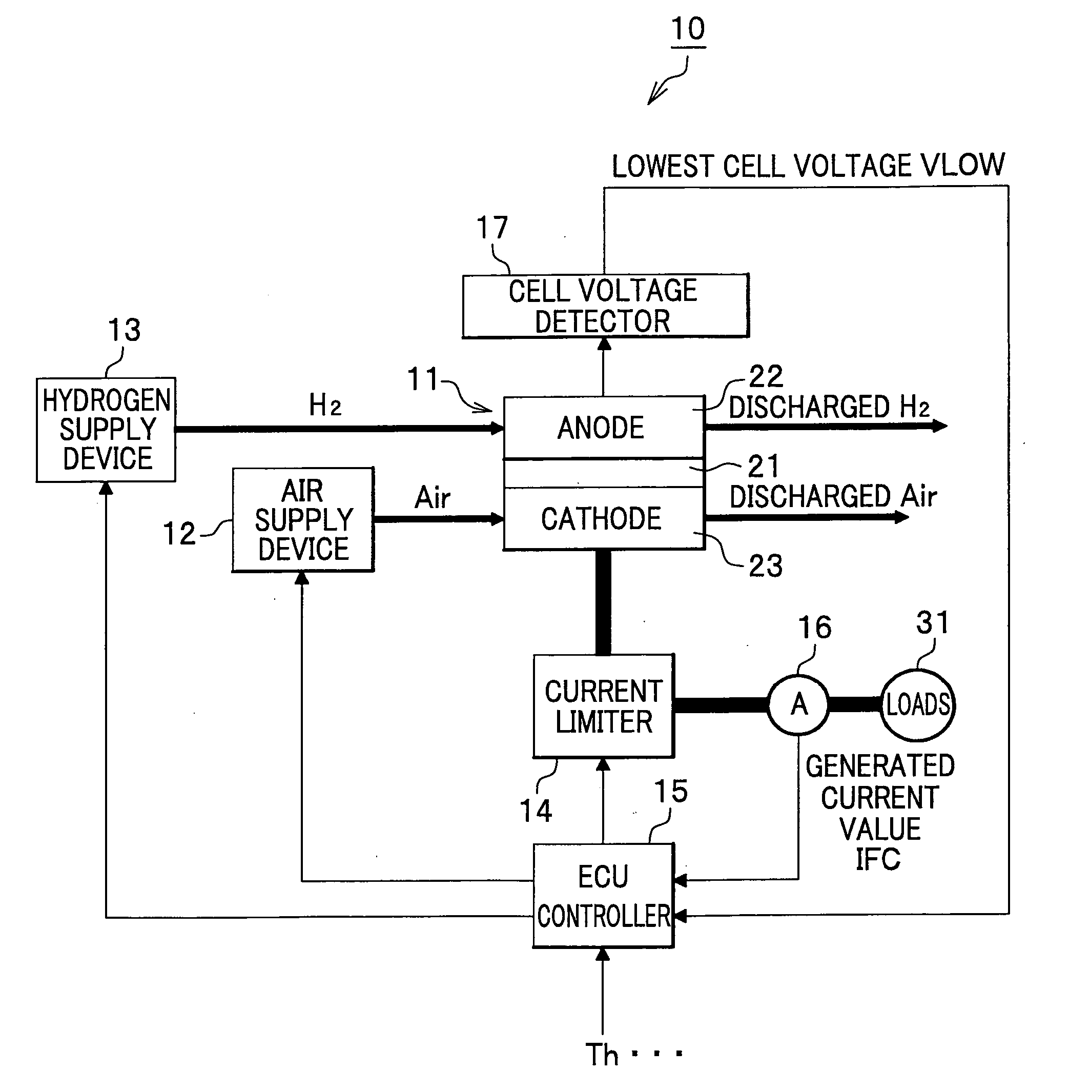
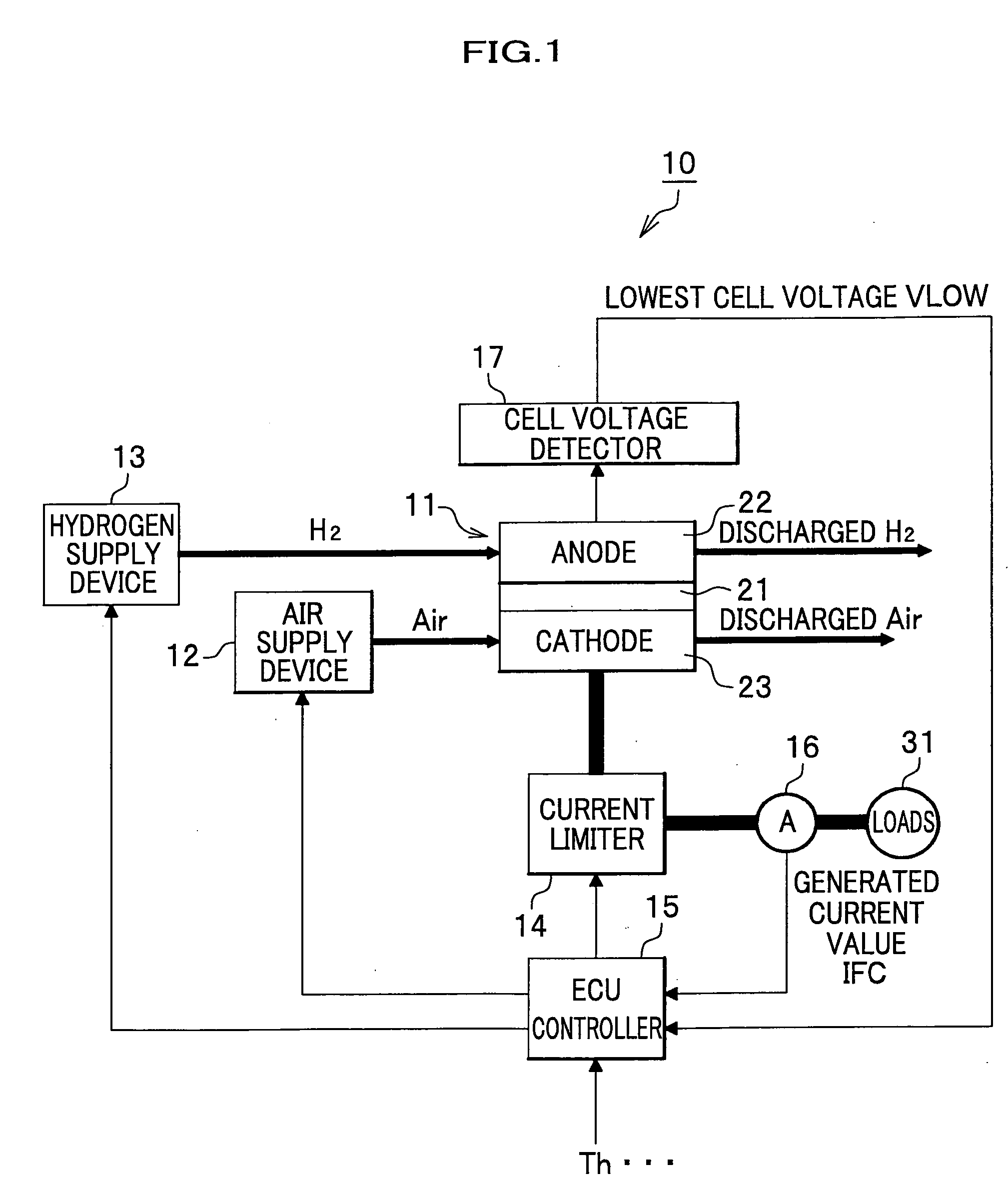
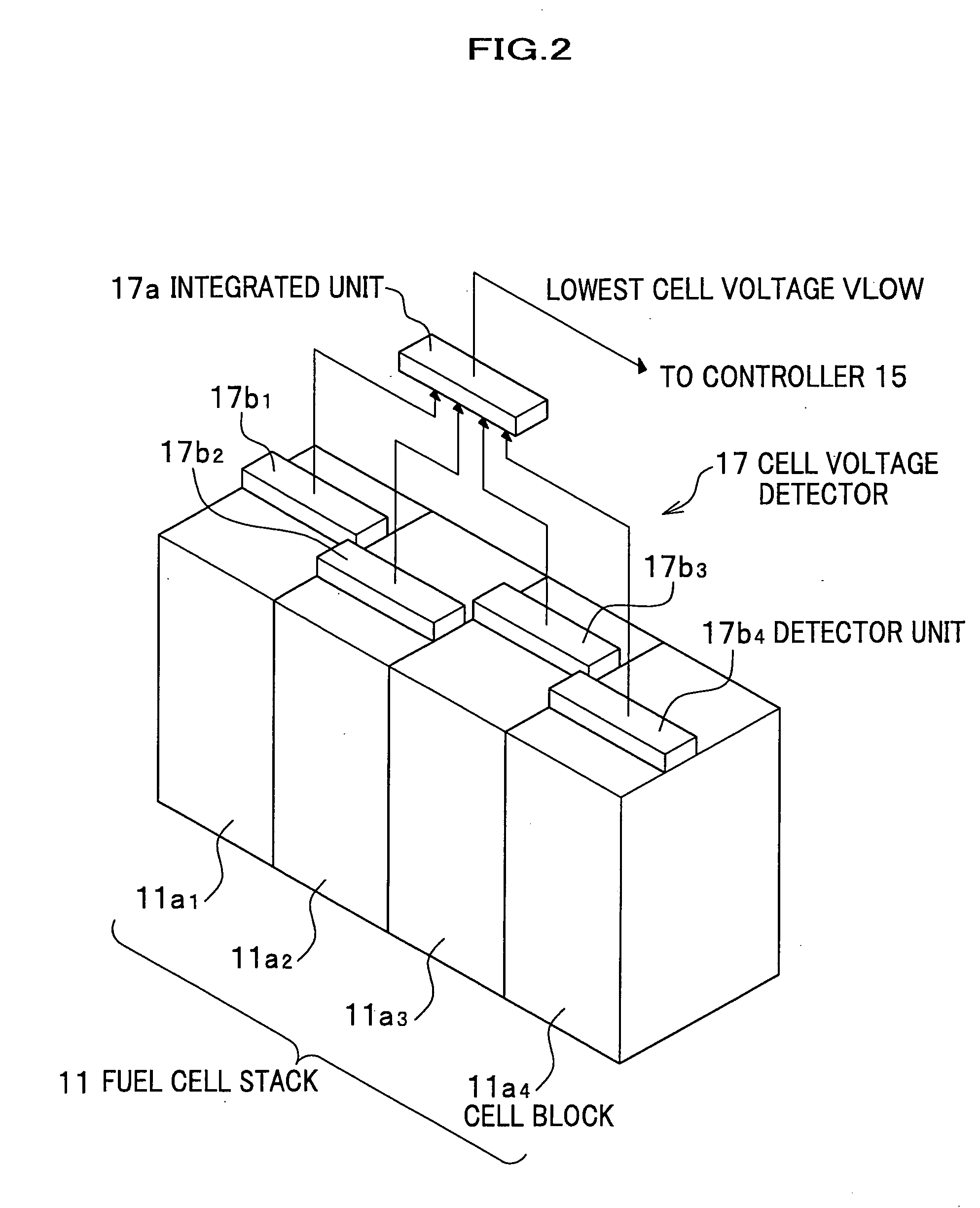
[0025] As shown in FIG. 1, a fuel cell system 10 includes a fuel cell stack 11, an air supply device 12 for feeding air as an oxidant to the fuel cell stack 11, a hydrogen supply device 13 for feeding hydrogen as fuel to the fuel cell stack 11, a current limiter 14 for controlling an electric current (generated current value) taken out from the fuel cell stack 11, a controller 15 for controlling the overall fuel cell system 10, a current detector 16 for detecting the amount of electric current (generated current value) taken out from the fuel cell stack 11, and a cell voltage detector 17 for detecting a voltage (cell voltage) of each single cell of the fuel cell stack 11. This fuel cell system 10 is mounted on a vehicle (not shown).

[0026] In this embodiment, the cur...


PUM

PropertyMeasurementUnit
temperatureaaaaaaaaaa
cell voltageaaaaaaaaaa
voltageaaaaaaaaaa

Abstract

A current limiting system for fuel cells, which limits electric current generated by a fuel cell stack including a plurality of single cells generating electricity by a chemical reaction between fuel gas and oxidant. The current limiting system includes: a cell voltage detector which detects a cell voltage of each single cell; a current detector which detects a generated current taken out from the fuel cell stack; an input device through which are inputted the cell voltage and the generated current value; a target current limit value setting device which sets a target current limit value for limiting the generated current taken out from the fuel cell stack in accordance with the cell voltage; a current limit value setting device which sets a current limit value by replacing a present current limit value with the target current limit value when a difference between the present current limit value and the generated current value becomes smaller than a first predetermined value; and an output device which outputs the current limit value either to a current limiter for limiting the generated current in accordance with the current limit value or to an electric power consumption controller for controlling electric power consumption of loads that consume the generated current.

Description

BACKGROUND OF THE INVENTION [0001] The present invention relates to a current limiting system and a current limiting method for fuel cells, for limiting electric current generated by a fuel cell stack in accordance with an electricity-generation condition of the fuel cell stack. [0002] Fuel cell includes a solid polymer electrolyte membrane sandwiched between a hydrogen pole at one side of the membrane and an oxygen pole at the other side of the membrane to provide a membrane electrode assembly (MEA), which is further sandwiched between conductive separators to form a single cell. Several tens or several hundreds of single cells are stacked to form a fuel cell stack. In order to generate electricity stably and constantly in this kind of fuel cell stack, the fuel cell stack has to be driven under a certain constant temperature, for example, at 80° C., and as disclosed in Japanese Laid-open Patent Application No. 7-272736 (paragraphs [0019] and [0020]), all the cell voltages are monit...

Claims


Application Information

Patent Timeline
Patent Type & Authority Applications(United States)
IPC IPC(8): H01M8/00H01M8/10H01M8/04
CPCH01M8/04552Y02E60/50H01M8/0491H01M8/04589
Inventor IGARASHI, DAISHIKIMURA, KENICHIROMURAKAMI, YOSHIKAZUWAKE, CHIRHIROUEDA, KENICHIRO
Owner HONDA MOTOR CO LTD
Learn More