
Method for producing three-dimensional sintered work pieces

a three-dimensional sintered work and work piece technology, applied in the direction of additive manufacturing process, electric/magnetic/electromagnetic heating, coating, etc., can solve problems such as work piece destruction, and achieve the effect of reliably avoiding work piece distortion

Inactive Publication Date: 2005-06-30
CL SCHUTZRECHTSVERW
View PDF13 Cites 139 Cited by
  • Summary
  • Abstract
  • Description
  • Claims
  • Application Information

AI Technical Summary

Benefits of technology

[0006] It is accordingly an object of the invention to provide a method for producing three-dimensional sintered work pieces which overcomes the above-mentioned disadvantages of the prior art methods of this general type, in which distortions of the work pieces is reliably avoided even when relatively large work pieces are being produced.
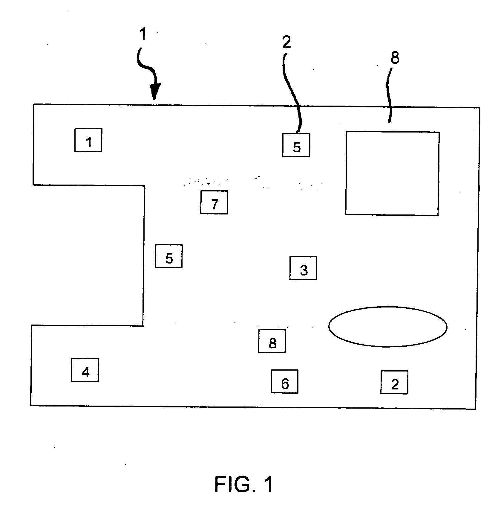
[0008] One of the core concepts of the invention is the successive irradiation of the individual sections, such that successively irradiated individual sections are at a distance from one another which is greater than or at least equal to the mean diameter of an individual section. In particular, the individual sections should be successively irradiated in a stochastic distribution and the distance between them should be such that the introduction of heat into the layer that occurs as a result of the thermal irradiation is substantially uniform. This avoids stresses, which in the prior art have in some cases even resulted in individual layers not being correctly joined to one another but rather breaking off or flaking away in layers, leading to destruction of the work piece.
[0012] Moreover, it may be advantageous for the edges of the individual sections, after irradiation of the inner regions of the individual sections, additionally to be exposed to a peripheral irradiation.
[0015] Furthermore, it may be advantageous for the edge region of the work piece to be sintered with a higher density, and in particular the density in the edge region may approximately correspond to the density of the grid structure in the work piece core region. The higher density can be achieved by substantially complete melting of the sintering material in the edge region. The higher density can also be sintered into the region of inner surfaces at work pieces passages, screw threads which are to be machined in or the like, so that work piece passages and work piece surfaces can be re-machined, in particular by chip-forming or grinding machining.
[0017] In more extensively structured work piece regions, it is advantageous for longer time periods to be left between the laser irradiation of adjacent sintered sections than in the case of sintered regions that are of a flatter configuration.

Problems solved by technology

This avoids stresses, which in the prior art have in some cases even resulted in individual layers not being correctly joined to one another but rather breaking off or flaking away in layers, leading to destruction of the work piece.

Method used


Image

  • Method for producing three-dimensional sintered work pieces
  • Method for producing three-dimensional sintered work pieces
  • Method for producing three-dimensional sintered work pieces

Examples


Embodiment Construction

[0027] Referring now to the figures of the drawing in detail and first, particularly, to FIG. 1 thereof, there is shown a method according to the invention for producing three-dimensional sintered work pieces 1, which in particular is a stereolithography method for use in an automated laser sintering unit. First, a sintering material is applied to a substrate in layers 8 from a storage device. The sintering material may be liquid, pasty, pulverulent or granular. Then, the sintering material is heated by regional irradiation of defined individual sections 2, in such a manner that the constituents of the sintering material, with complete or at least partial melting, are joined to one another as a function of irradiation regions to form the work piece 1.

[0028] As can be seen from the plan view of the work piece 1 shown in FIG. 1, the individual sections 2 which are irradiated successively in terms of time are at a distance from one another that is greater than or at least equal to a m...


PUM

PropertyMeasurementUnit
Lengthaaaaaaaaaa
Timeaaaaaaaaaa
Diameteraaaaaaaaaa

Abstract

A method for producing three-dimensional sintered work pieces, in particular a stereo lithography method for application in a laser sinter machine, in which a sinter material, in particular liquid, pasty, powder or granular sinter material is applied in layers from a reservoir onto a backing and heated by partial irradiation of prescribed individual sections such that the components of the sinter material are combined to give the work piece by partial or complete fusion in regions dependent on the irradiation. The serially irradiated individual sections have a separation from each other, greater than or at least equal to average diameter of the individual sections.

Description

CROSS-REFERENCE TO RELATED APPLICATION [0001] This application is a continuation, under 35 U.S.C. § 120, of copending international application No. PCT / DE01 / 04055, filed Oct. 30, 2001, which designated the United States.BACKGROUND OF THE INVENTION FIELD OF THE INVENTION [0002] The invention relates to a method for producing three-dimensional sintered work pieces, in particular to a stereolithography method, which can be used in an automated sintering unit, in particular an automated laser sintering unit. [0003] Published, European Patent Application EP 0 171 069 A discloses a method in which a layer of sintering material is applied to a substrate or to a layer which has already been consolidated and is consolidated by irradiation using a targeted laser beam. As a result, the three-dimensional sintered work piece is built up in layers. Express reference is made to the disclosure of EP 0 171 069 A, and the content of the disclosure of this European application is incorporated by refer...

Claims


Application Information

Patent Timeline
IPC IPC(8): B22F3/105B22F3/16B29C67/00
CPCB29C67/0077B29C64/153B22F2207/17Y02P10/25B22F10/38B22F10/12
Inventor HERZOG, FRANK
Owner CL SCHUTZRECHTSVERW
Learn More