
Fuel cell

a fuel cell and fuel cell technology, applied in the field of fuel cells, can solve the problems of exposing the electrolyte to damage from the gas-diffusion layer, difficult to control the surface pressure involving contact resistance reduction, and low strength of carbon paper surface pressure resistan

Active Publication Date: 2005-06-16
HONDA MOTOR CO LTD
View PDF2 Cites 8 Cited by
  • Summary
  • Abstract
  • Description
  • Claims
  • Application Information

AI Technical Summary

Benefits of technology

[0008] Accordingly, an aspect of the present invention is to provide a fuel cell wherein biting by an electrode layer into a gas-diffusion layer due to a pressing force is suppressed or prevented during formation of a stack.
[0010] Because the surface roughness of the first and second gas-diffusion layers is set as described above, irregularity of the surface is reduced, which prevents the first electrode layer from biting into the first gas-diffusion layer and / or the second electrode layer from biting into the second gas-diffusion layer, due to a pressing force during formation of a stack. Thus, a fuel cell is provided wherein damage to the electrolyte by the gas-diffusion layers is prevented.
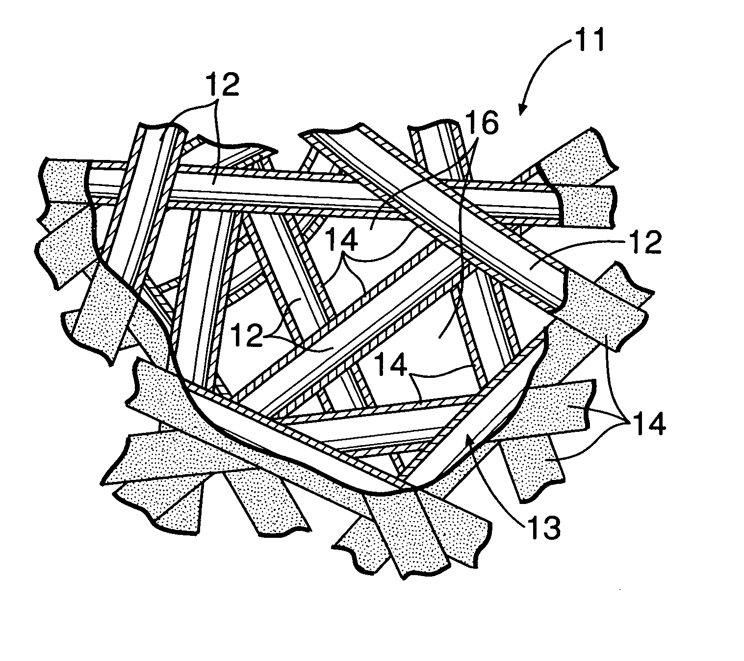
[0011] According to a second feature of the present invention, the air-permeable metallic material includes a main body formed from an aggregate of metal fibers. A coating made of a noble metal and defining the arithmetic average roughness Ra is deposited on each metal fiber in a surface of the main body on the side contacting the electrode. With the second feature, the irregularity of the surfaces of the gas-diffusion layers is reduced.
[0012] According to a third feature of the present invention, a low electric-resistance layer formed from one of copper and a noble metal is provided on each metal fiber in a surface of the main body on the side contacting the separator plate. With the third feature, the contact resistance between the first gas-diffusion layer and the first separator plate, as well as between the second gas-diffusion layer and the second separator plate, is reduced.
[0014] According to a fifth feature of the present invention, the first and second separator plates are made of a metal. Also, the first gas-diffusion layer is thermo-compression bonded to the first separator plate, while the second gas-diffusion layer is thermo-compression bonded to the second separator plate. With the fifth feature, an electric connection between the first separator plate and the first gas-diffusion layer, as well as between the second separator plate and the second gas-diffusion layer, is extremely reliable.
[0015] According to a sixth feature of the present invention, a water-repellent layer is formed on each metal fiber. With the sixth feature, clogging of the first and second gas-diffusion layers due to produced water is prevented.

Problems solved by technology

However, carbon paper is typically low in strength and surface pressure resistance, and moreover, is brittle.
Therefore, during formation of a stack in the conventional fuel cell, control of the surface pressure involving contact resistance reduction is extremely difficult to accomplish.
However, in such a conventional gas-diffusion layer, because the diameter of fine pores in a surface of the gas-diffusion layer on a side contacting an electrode is relatively large, portions of an electrode layer and an electrolyte bite deeply into the fine pores due to a pressing force that is generated during formation of a stack, exposing the electrolyte to damage from the gas-diffusion layer.

Method used


Image

  • Fuel cell
  • Fuel cell
  • Fuel cell

Examples


Embodiment Construction

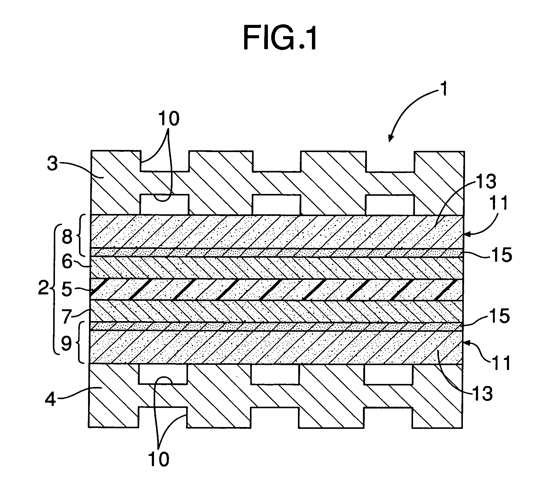
[0027] Referring to FIG. 1, a polymer electrolyte fuel cell 1, according to a preferred embodiment of the present invention, includes a laminated plate-shaped membrane electrode assembly 2 and an upper first separator plate 3 and a lower second separator plate 4 sandwiching the membrane electrode assembly 2 therebetween. The membrane electrode assembly 2 includes a polymer electrolyte membrane (electrolyte) 5; an upper first electrode layer 6 and a lower second electrode layer 7 sandwiching the polymer electrolyte membrane 5 therebetween; and an upper first gas-diffusion layer 8 and a lower second gas-diffusion layer 9 disposed on the outer sides of electrode layers 6 and 7, respectively, that do not sandwich the electrolyte membrane 5. The polymer electrolyte membrane 5 is made of, for example, Nafion® (manufactured by DuPont) which is a fluorocarbon resin ion exchange membrane. Each of the first electrode layer (e.g., an anode) 6 and the second electrode layer (e.g., a cathode) 7 ...


PUM


Abstract

A fuel cell includes a laminated, plate-shaped membrane electrode assembly and first and second separator plates sandwiching the membrane electrode assembly. The membrane electrode assembly includes a polymer electrolyte membrane; first and second electrode layers sandwiching the polymer electrolyte membrane; and first and second gas-diffusion layers disposed on an outer side of the electrode layers, respectively. The first and second gas-diffusion layers are made of an air-permeable metallic material. An arithmetic average roughness Ra of a surface of the air-permeable metallic material on the side contacting one of the electrode layers is in a range of 0.1 μm≦Ra≦1.0 μm.

Description

RELATED APPLICATION DATA [0001] The Japanese priority application No. 2003-392201 upon which the present application is based is hereby incorporated in its entirety herein by reference. BACKGROUND OF THE INVENTION [0002] 1. Field of the Invention [0003] The present invention relates to a fuel cell. [0004] 2. Description of the Related Art [0005] A conventional fuel cell includes a laminated, plate-shaped membrane electrode assembly and first and second separator plates, which sandwich the membrane electrode assembly therebetween. The membrane electrode assembly includes an electrolyte; first and second electrode layers sandwiching the electrolyte therebetween; and first and second gas-diffusion layers disposed outside the electrode layers, respectively, relative to the electrolyte. Each gas-diffusion layer is generally made of a carbon paper. However, carbon paper is typically low in strength and surface pressure resistance, and moreover, is brittle. Therefore, during formation of a...

Claims


Application Information

Patent Timeline
IPC IPC(8): H01M4/86H01M4/92H01M8/02H01M8/10
CPCH01M4/8605Y02E60/521H01M8/1004H01M4/92Y02E60/50
Inventor KAMACHI, ATSUSHIITAMI, SHUNSUKEOKANOBORI, HITOSHI
Owner HONDA MOTOR CO LTD
Learn More