
Surface acoustic wave device and manufacturing method thereof

Inactive Publication Date: 2005-06-16
ALPS ALPINE CO LTD
View PDF2 Cites 18 Cited by
  • Summary
  • Abstract
  • Description
  • Claims
  • Application Information

AI Technical Summary

Benefits of technology

[0015] The present invention is contrived to solve the above conventional problems, and it is an object of the present invention to provide a surface acoustic wave device capable of improving a temperature characteristic and keeping an excellent resonance characteristic and a manufacturing method thereof.

Problems solved by technology

However, the surface acoustic wave device and the manufacturing method thereof disclosed in Patent Document 1 have the following problems.
However, such figure is only a schematic diagram and does not reflect the surface structure of the actual surface acoustic wave device.
In addition, when the SiO2 film 3 is formed using an RF sputtering method, cracks 3c or voids are formed at the inside of the SiO2 film 3, specifically around the interdigital electrodes 2, whereby the propagation efficiency of the surface acoustic waves is deteriorated, thereby increasing the energy loss of the resonator.

Method used


Image

  • Surface acoustic wave device and manufacturing method thereof
  • Surface acoustic wave device and manufacturing method thereof
  • Surface acoustic wave device and manufacturing method thereof

Examples


embodiments

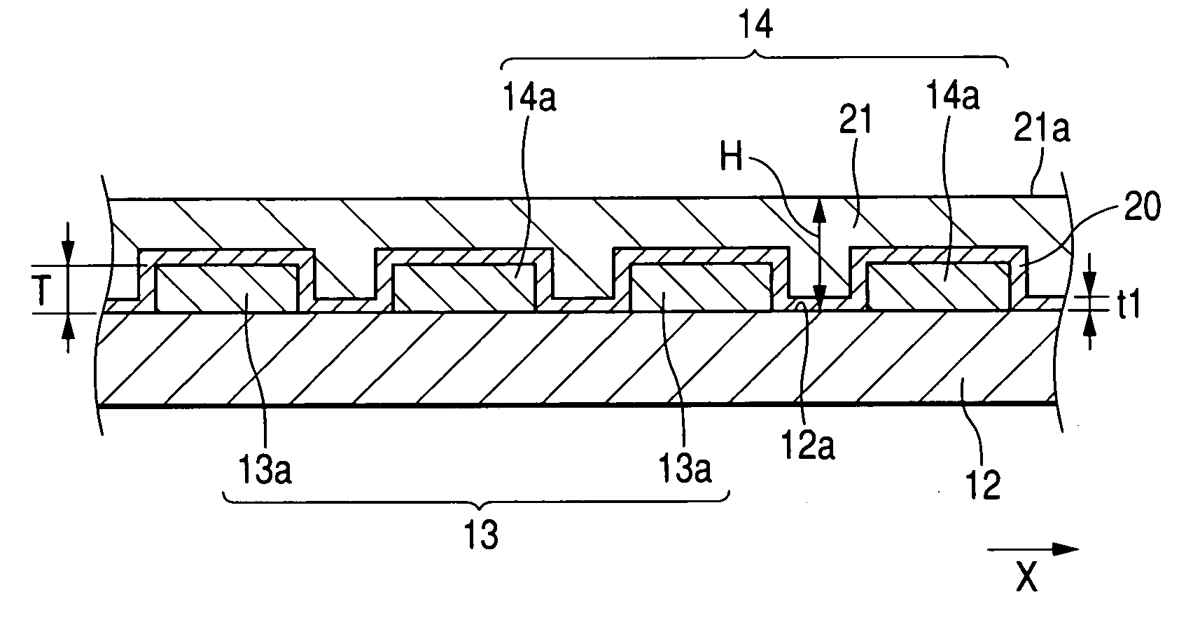
[0132]FIG. 21 shows a sectional photograph of the surface acoustic wave device according to the present invention, in which the insulating layer covering the piezoelectric substrate and the interdigital electrode portions is formed using the spin-on-glass method.

[0133] The interdigital electrode portions are formed on the piezoelectric substrate made of LiTaO3 using the conductive material Cu, Al, Au, etc. using the frame plating method, etc., and the insulating thin film 20 having a thickness of 20 nm to 40 nm is formed on the piezoelectric substrate 12 and the interdigital electrode portions 13 and 14 using the sputtering method. Next, polysilazane (produced by Clariant Japan Co., Ltd.) is applied using the spin coating method, then dibytyl ether solvent is removed by baking the coating film in an atmosphere of nitrogen at a temperature of 150° C. for 3 minutes, and then a curing process is performed in an atmosphere of H2O at a temperature of 400° C. for an hour. Through this cu...


PUM


Abstract

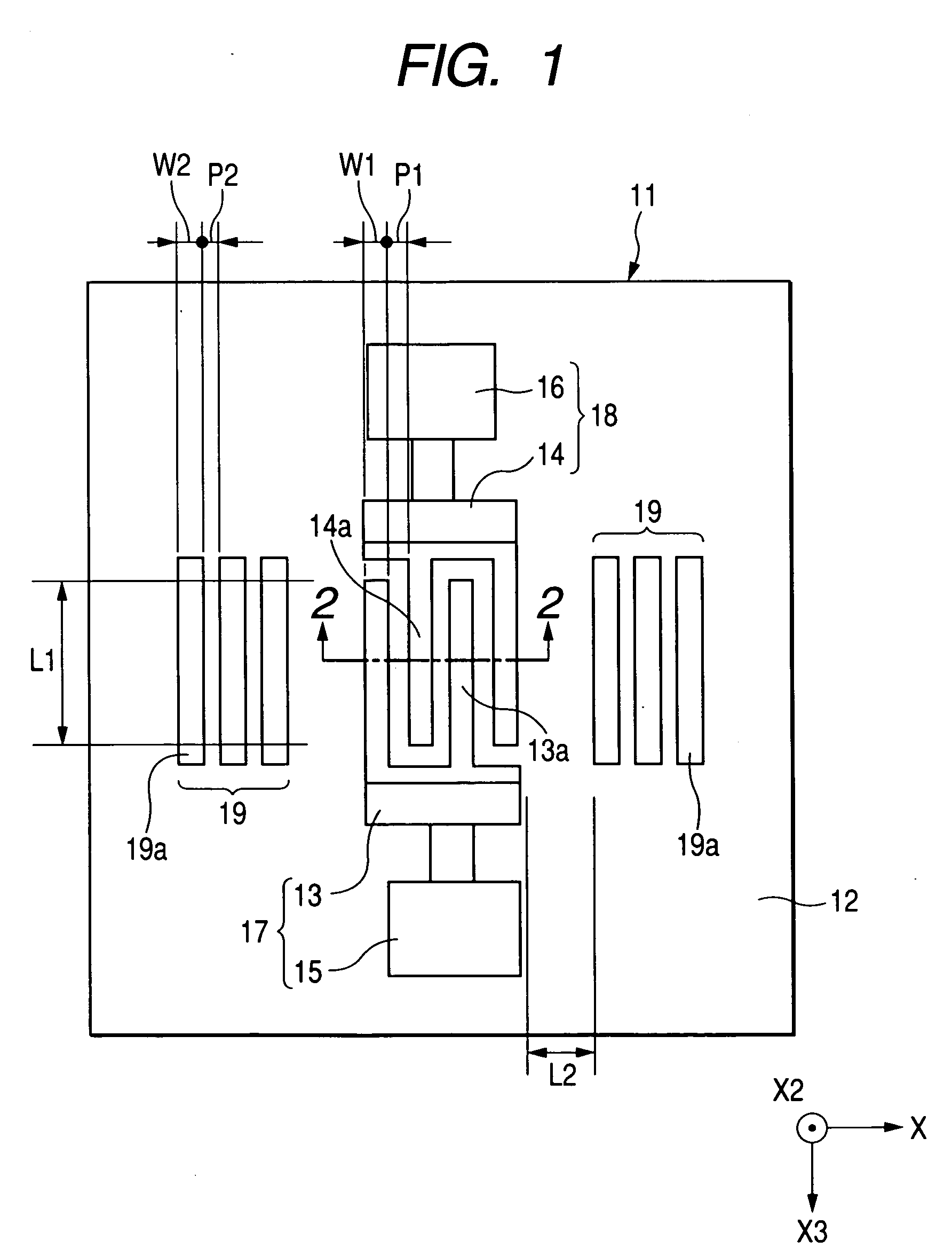
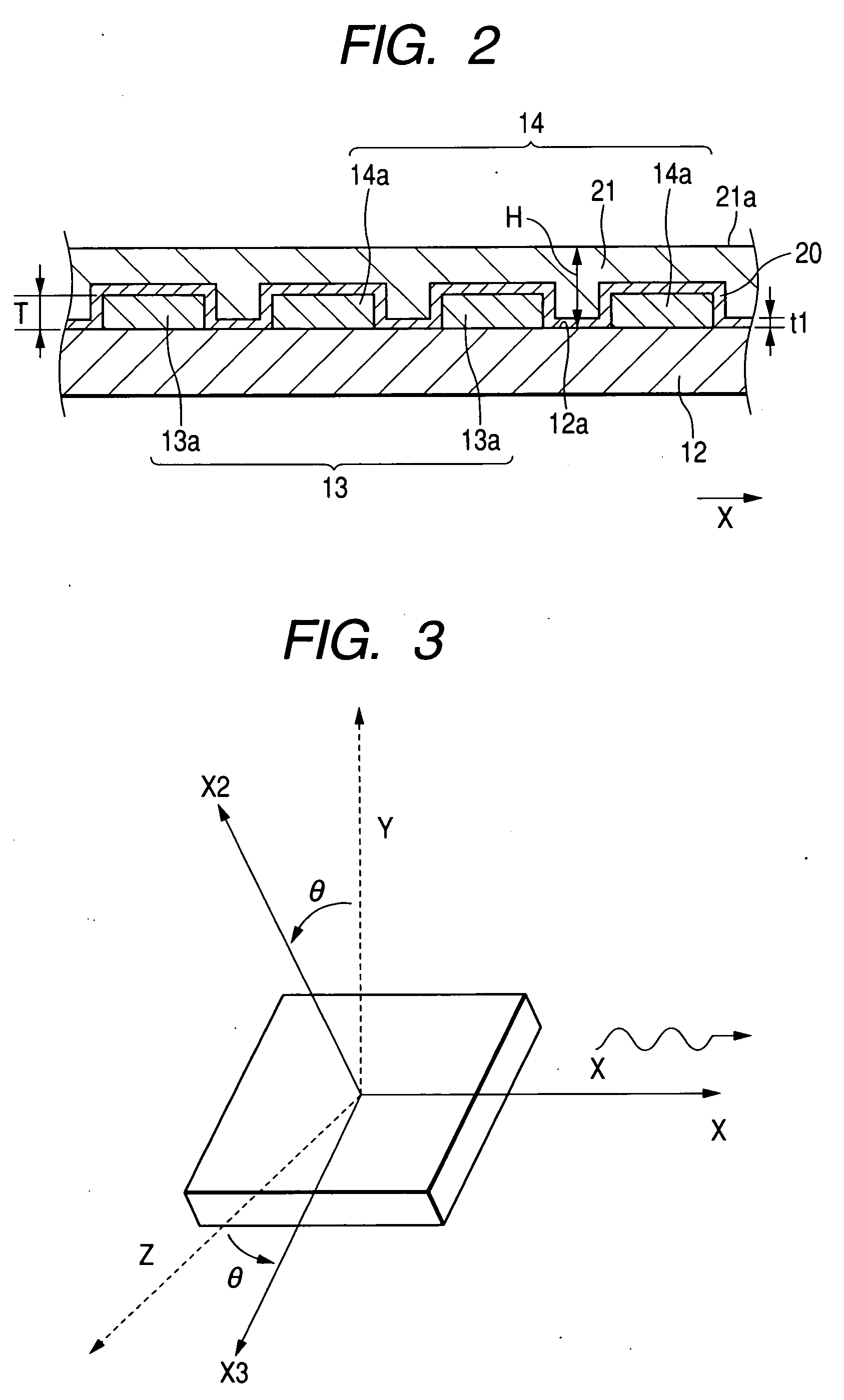
A piezoelectric substrate and interdigital electrode portions are covered with an insulating layer with an insulating thin film interposed therebetween. The piezoelectric substrate is made of LiTaO3 and the insulating thin film and the insulating layer are made of silicon oxide. By intentionally making the upper surface of the insulating layer flat, the deterioration of propagation efficiency of surface acoustic waves can be suppressed, so that it is possible to reduce increase in insertion loss of a resonator. Since the upper surface of the insulating layer is flat, it is also possible to reduce variation in resonant frequency and anti-resonant frequency due to the temperature change of the surface acoustic wave device.

Description

BACKGROUND OF THE INVENTION [0001] 1. Field of the Invention [0002] The present invention relates to a surface acoustic wave device capable of improving a temperature characteristic at a high-frequency band and a manufacturing method thereof. [0003] 2. Description of the Related Art [0004] Surface acoustic wave devices are electronic components using surface acoustic waves which are propagated in a state where mechanical vibration energy is concentrated only around surfaces of solid substances, and are used to construct filters, resonators, duplexers, etc. [0005] Recently, decrease in size and decrease in weight of mobile communication terminals such as mobile phones have been advanced, and thus decrease in size of electronic components mounted on the mobile communication terminals has been required. [0006] A surface acoustic wave device has a structure where a pair of interdigital electrodes (IDT (InterDigital Transducer) electrodes) made of a conductive material having a small spe...

Claims


Application Information

Patent Timeline
IPC IPC(8): H03H3/08H03H9/145H03H3/10H03H9/02
CPCH03H9/02834
Inventor OZAKI, KYOSUKETAKAHASHI, HIDEYUKISATO, TAKASHIWAGA, SATOSHIIKEDA, TAKESHIMEGURO, TOSHIHIRO
Owner ALPS ALPINE CO LTD
Learn More