Cylinder head gasket

Inactive Publication Date: 2005-06-16
UCHIYAMA MFG +2
View PDF11 Cites 23 Cited by
  • Summary
  • Abstract
  • Description
  • Claims
  • Application Information

AI Technical Summary

Benefits of technology

[0020] According to the first aspect of the invention, the bead is made of a rubber material superior in fluidity in processing and the groove is formed by means of post processing such as compression of the compound layer, so that the design modification of groove in shape and size and so on is flexible and its production is more facilitated. Accordingly, a complexly shaped bead such as narrow one or one with many branches can be formed.
[0021] The bead can be formed in variable shapes and sizes and the rubber material inserted into the groove gets in touch with the bottom and both sides thereof three-dimensionally, so that the rubber material is not easily peeled off and has strong jointing force, thereby securing superior durability.
[0022] Further according to such gasket of the present invention that concave shoulders are formed at both edges of the groove, the concave shoulder serves as an escape hole for pushing and deforming the rubber material when the bead is excessively compressed.
[0023] Still further according to such gasket of the present invention that the concave shoulders and the groove are coincidentally formed by pressing the corresponding region with the molding die, its productivity is more facilitated.
[0024] Such concave shoulders can be also coincidentally formed at the formation process of the groove by using the molding die with a pressing part for concave shoulder. According to usage of such molding die, a special die and a forming process for the concave shoulder can be saved, thereby realizing cheaper manufacturing.
[0025] According to the second aspect of the present invention, it is not required to coincidentally and integrally form the compound layer and the bead, so that its productivity is facilitated. Further in this gasket, the bead is made of a rubber material that is excellent in fluidity when being processed, thereby enabling to be produced in an optional shape. Further the groove is formed by a post process of removing a part of compound layer, forming of the compound layer itself can be facilitated and the design modification in shape and size and so on can be also facilitated. Accordingly, a bead with complex shape such as a narrow bead or a bead with many branches may be easily manufactured.

Problems solved by technology

However, it is very difficult or practically impossible to form both of a compound layer and a bead simultaneously in a body as shown in the latter prior art, because such a compound material containing fiber material and rubber is inferior to the simple rubber material in the point of fluidity.
According to the manner described above, there is a defect of restriction to the size such that some kinds of bead with small width like a narrow convex bead cannot be produced because the core material plate itself is required to be bent.
Further there is a limit of utilization such that a gasket to be installed to a small size engine where the screwing force between the cylinder block and the cylinder head is small cannot be provided because the reaction force from the bent core material plate is strong.
As disclosed in JP-U-62-0077366 in which a bead is formed by bending the core material plate, because there is restriction of the size or the shape of a bead such that a bead with a narrow convex section or a narrow bead cannot be produced and further there is a limit of utilization such that a gasket to be installed to a small size engine of which screwing force of the cylinder block and the cylinder head is weak cannot be provided because the reaction force from the bent core material plate is strong, it has poor usability.
However, the bead is formed to be projected by compressing the other parts than the bead into the thickness direction with a molding die, so that the material density of that bead becomes low.
Accordingly, supposing that the material strength of bead becomes smaller than the other parts there around and the bead is originally formed with a compound material with compressibility, if such a “weakening” bead is applied to the cylinder head gasket under severe requirement, the sealing ability of the gasket will not be improved.
As a countermeasure, the projecting amount of bead may be made large, however, in such a case, the bead fallen down a chunk causes a gap when the gasket is screwed between the cylinder block and the cylinder head.

Method used


Image

  • Cylinder head gasket
  • Cylinder head gasket
  • Cylinder head gasket

Examples


embodiment 1

[Preferred Embodiment 1]

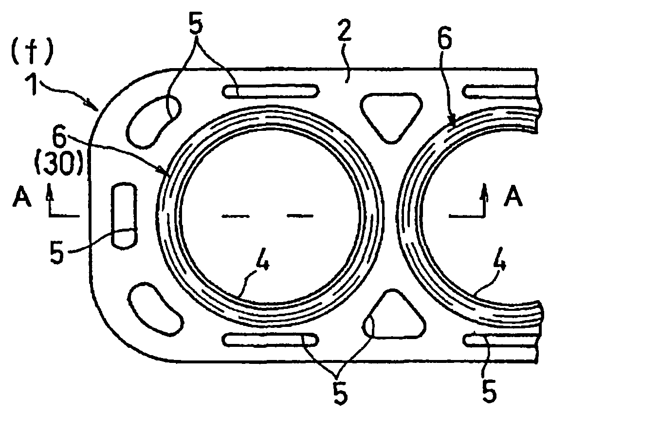
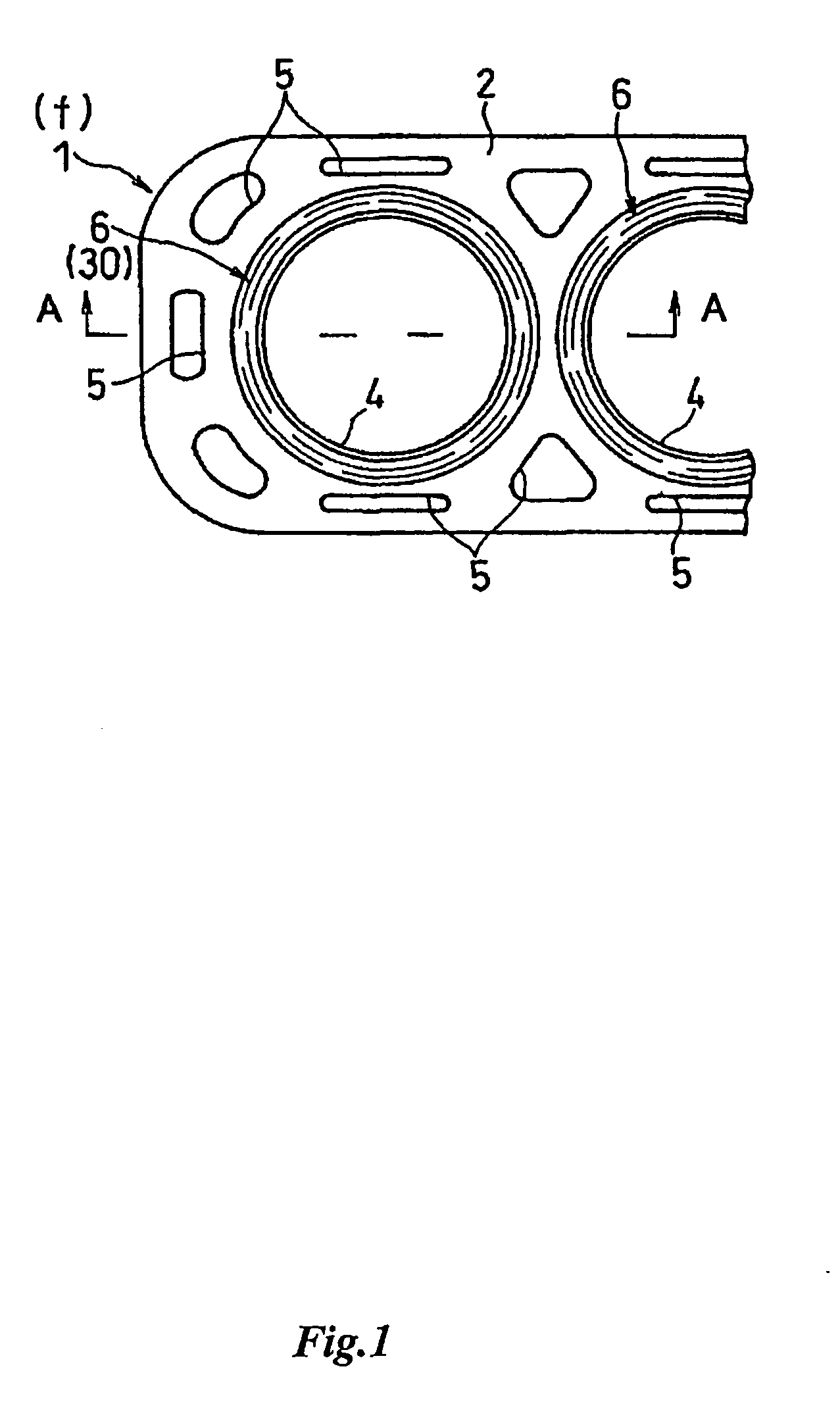
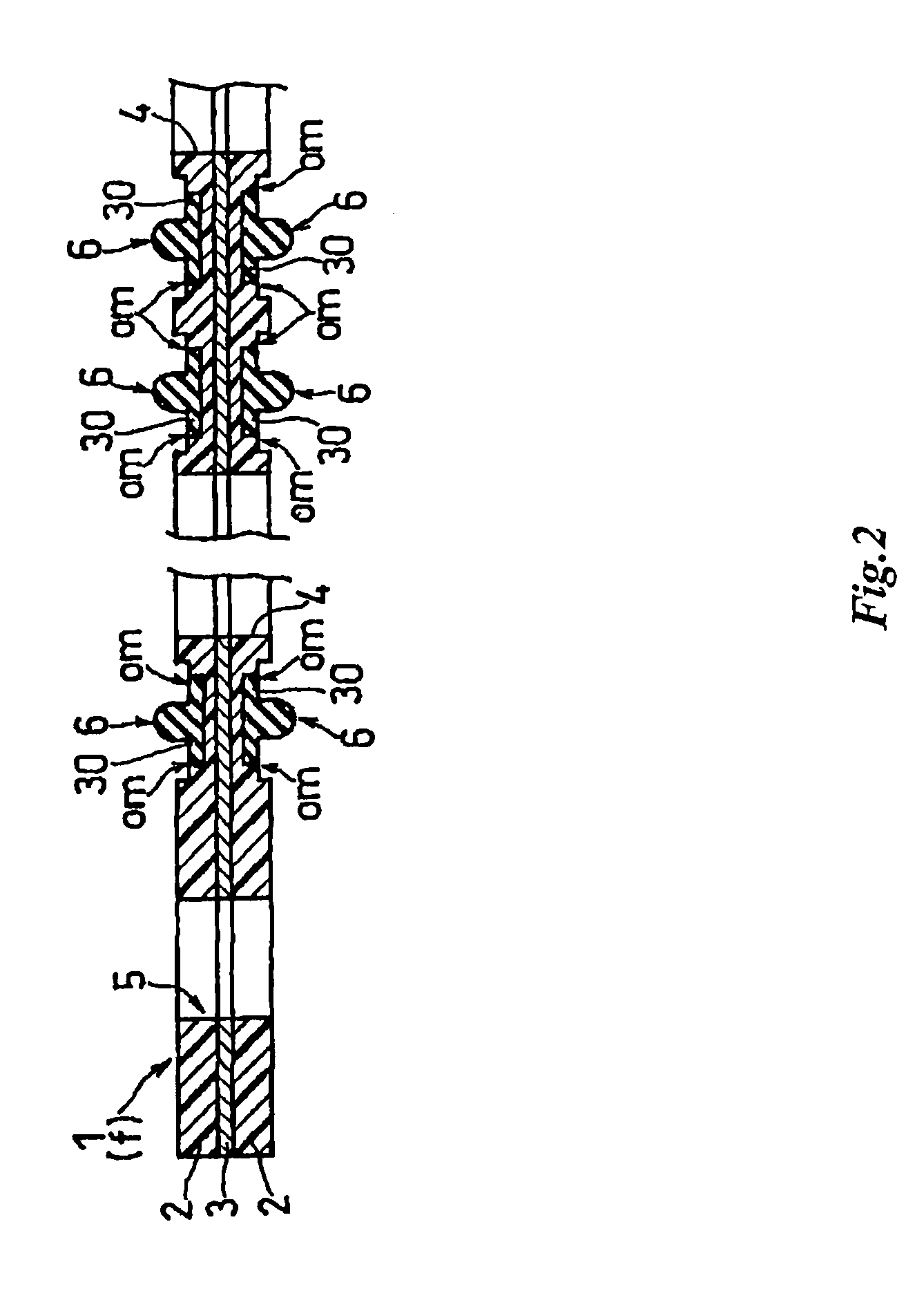
[0060]FIG. 1 and FIG. 2 show a cylinder head gasket 1 intervened between a cylinder block and a cylinder head of an engine. The cylinder head gasket 1 is a double-sided rubber coat metal gasket made of a composite base plate f comprising a core material plate 3 like SPCC (cold rolled steel sheet) and a compound layer 2 which is formed such that a fiber material as a reinforcing material is mixed with a rubber to be coated on the upper and lower surfaces of the core material plate 3.

[0061] The fiber material includes an inorganic fiber like glass fiber, ceramic fiber, asbestos, mineral wool, soluble quartz fiber, chemical treating high silica fiber, fused aluminum silicate fiber, alumina continuous fiber, stabilized zirconia fiber, boron nitride fiber, titanic acid alkali fiber, whisker, carbon fiber, metal fiber, boron fiber and so on. The fiber material also includes an organic fiber like aromatic polyamide fiber, polyamide fiber, polyolefin fiber, polyacry...

embodiment 2

[Preferred Embodiment 2]

[0077] The concave shoulder om may be formed by pressing the side area 2b of the compound layer 2 with a press mold 12 for groove when the groove m is formed by compressing the compound layer 2. That is, as shown in the cylinder head gasket 1 in FIG. 8 and FIG. 9, small projections 14 are provided for forming the concave shoulders at both sides of a projection 13 for forming groove of the upper press mold 12, so that the concave shoulder om is simultaneously formed when the groove m is formed (see FIG. 8). The rubber material 30 is injected into the groove m and is molded with the mold 8, then the bead structure 6 having the concave shoulders (recess groove) om at both sides are formed (see FIG. 9).

embodiment 3

[Preferred Embodiment 3]

[0078] The cylinder head gasket 1 may be constructed such that the concave shoulder om is formed with the area of the rubber material 30 injected for forming the bead structure 6. The groove m is formed with the press mold 7 like the preferred embodiment of the present invention (see FIG. 8), however, a mold 15 for injection molding has a small projection 17 for forming the concave shoulder at both sides of a recess part 16 for forming the bead structure (see FIG. 9). Thus, the cylinder head gasket 1 having the concave shoulder (recess groove) om within the area of the rubber material 30 is formed by the mold 15.


PUM


Abstract

A cylinder head gasket for sealing between a cylinder block and a cylinder head, composed of a composite base plate, the composite base plate comprising a core material plate and a compound layer formed on the front and back surfaces of the core material plate, the compound layer being formed by coating compound materials which contain a rubber and a fiber material. The cylinder head gasket is comprised of an annular groove which is formed by pressing the corresponding region around the cylinder bore of the compound layer, and a bead projecting from the surface of the compound layer which is formed by inserting the rubber material into the annular groove.

Description

FIELD OF THE INVENTION [0001] The present invention relates to a cylinder head gasket, more specifically to a cylinder head gasket for sealing between a cylinder block and a cylinder head, composed of a composite base plate and a compound layer formed on the front and back surfaces of the core material plate, which is formed by coating compound materials containing rubber mixed with fiber material. PRIOR ART [0002] Various cylinder head gaskets of this type have been known to public, for example, such gasket in which a compound layer which is made of a basic fiber comprised of a compressible inorganic fiber excluding asbestos, a rubber material and an inorganic filler is coated on the surface of the core material plate has been proposed and disclosed in JP-B-06-084785 and JP-A-63-096359. This type gasket has such advantages that its torque down is small when the gasket is screwed between the cylinder block and the cylinder head compared with gaskets simply formed by coating a rubber...

Claims


Application Information

Patent Timeline
IPC IPC(8): C09K3/10F02F11/00F16J15/12
CPCF16J15/122
Inventor MATSUKI, KATSUNORIHIMESAKI, MASASHIOGAKI, SHIGEOOMURA, SEIJIYASUKI, AKIRA
Owner UCHIYAMA MFG
Why Eureka
Try Eureka