Light emitting device and method of manufacturing the same
a technology of light-emitting devices and manufacturing methods, which is applied in the direction of organic semiconductor devices, sustainable manufacturing/processing, and final product manufacturing, etc., can solve the problems of short life of light-emitting devices, substrates are likely to be deformed, and plastic films are easily affected by heat, so as to reduce the stress of sealing films. , the effect of preventing a crack on the substra
- Summary
- Abstract
- Description
- Claims
- Application Information
AI Technical Summary
Benefits of technology
Problems solved by technology
Method used
Image
Examples
embodiment mode 1
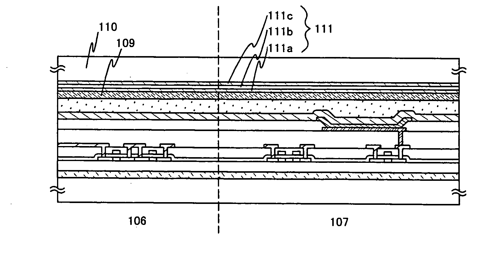
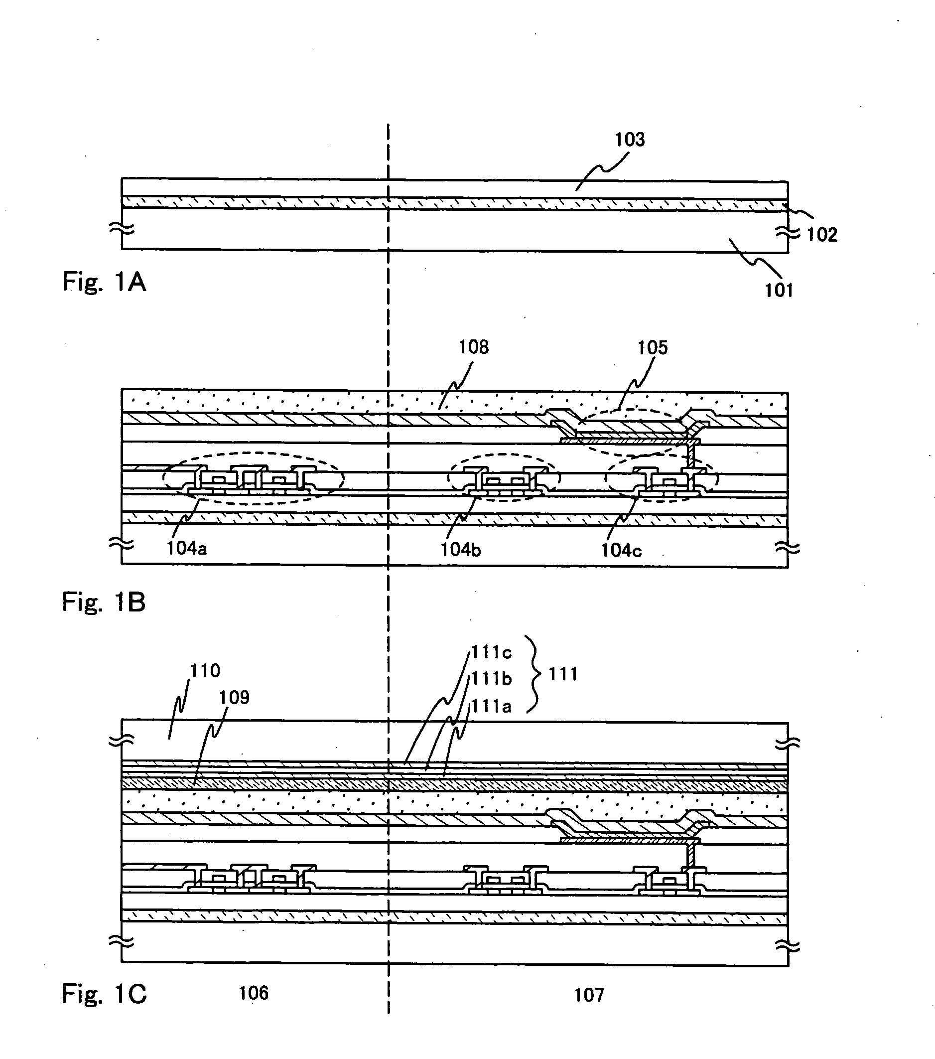
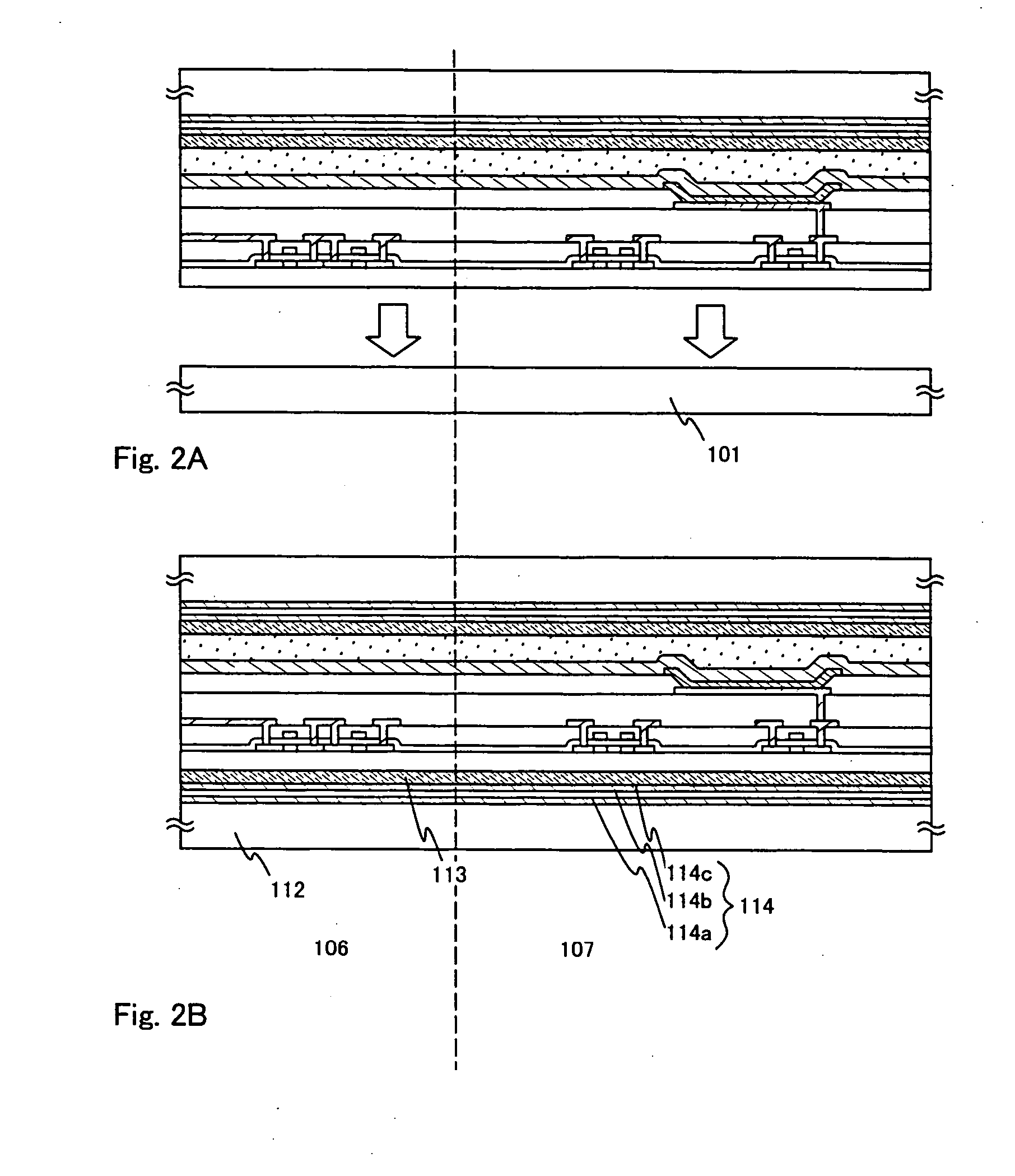
[0044] In FIG. 1A, a first bonding layer 102 made of an amorphous silicon film is formed to have a thickness of 100 to 500 nm (300 nm in this embodiment mode) on a first substrate 101. Although a glass substrate is used as the first substrate 101 in this embodiment mode, a quartz substrate, a silicon substrate, a metal substrate or a ceramic substrate may be alternatively used. Any material can be used for the first substrate 101 as long as it is resistant to a treatment temperature in the later manufacturing steps.
[0045] As a method of forming the first bonding layer 102, a low pressure thermal CVD method, a plasma CVD method, a sputtering method or an evaporation method may be used. On the first bonding layer 102, an insulating film 103 made of a silicon oxide film is formed to have a thickness of 200 nm. As a method of forming the insulating film 103, a low pressure thermal CVD method, a plasma CVD method, a sputtering method or an evaporation method may be used. The insulating ...
embodiment mode 2
[0089] Next, another embodiment mode of the present invention, which differs from the above-described first embodiment mode, will be described.
[0090] In FIG. 3A, a first bonding layer 202 made of an amorphous silicon film is formed to have a thickness of 100 to 500 nm (300 nm in this embodiment mode) is formed on a first substrate 201. Although a glass substrate is used as the first substrate 201 in this embodiment mode, a quartz substrate, a silicon substrate, a metal substrate or a ceramic substrate may be alternatively used. Any material can be used for the first substrate 201 as long as it is resistant to a treatment temperature in the later manufacture steps.
[0091] As a method of forming the first bonding layer 202, a low pressure thermal CVD method, a plasma CVD method, a sputtering method or an evaporation method may be used. On the first bonding layer 202, an insulating film 203 made of a silicon oxide film is formed to have a thickness of 200 nm. As a method of forming th...
embodiment 1
[0139] In Embodiment 1, the outward appearance of a light emitting device according to the present invention and its connection to an FPC will be described.
[0140]FIG. 5A shows an example of a top view of a light emitting device according to the present invention, described in Embodiment mode 1. A second substrate 301 and a third substrate 302 are both plastic substrates having flexibility. A pixel portion 303 and driving circuits (a source-side driving circuit 304 and a gate-side driving circuit 305) are provided between the second substrate 301 and the third substrate 302.
[0141] In FIG. 5A, there is shown an example where the source-side driving circuit 304 and the gate side-driving circuit 305 are formed on the substrate on which the pixel portion 303 is also formed. However, the driving circuits represented by the source-side driving circuit 304 and the gate side-driving circuit 305 may be formed on a different substrate from the substrate on which the pixel portion 303 is form...
PUM
 Abstract
Description
Claims
Application Information
 - R&D
- Intellectual Property
- Life Sciences
- Materials
- Tech Scout
- Unparalleled Data Quality
- Higher Quality Content
- 60% Fewer Hallucinations
Browse by: Latest US Patents, China's latest patents, Technical Efficacy Thesaurus, Application Domain, Technology Topic, Popular Technical Reports.
© 2025 PatSnap. All rights reserved.Legal|Privacy policy|Modern Slavery Act Transparency Statement|Sitemap|About US| Contact US: help@patsnap.com


