Variable valve actuating mechanism for internal combustion engine
a technology of internal combustion engine and variable valve, which is applied in the direction of machines/engines, couplings, lubricating auxiliaries, etc., can solve the problems of undesired variation in torque produced by internal combustion engine, affecting idling performance, and small lift quantity, so as to reduce non-uniform temperature distribution
- Summary
- Abstract
- Description
- Claims
- Application Information
AI Technical Summary
Benefits of technology
Problems solved by technology
Method used
Image
Examples
first embodiment
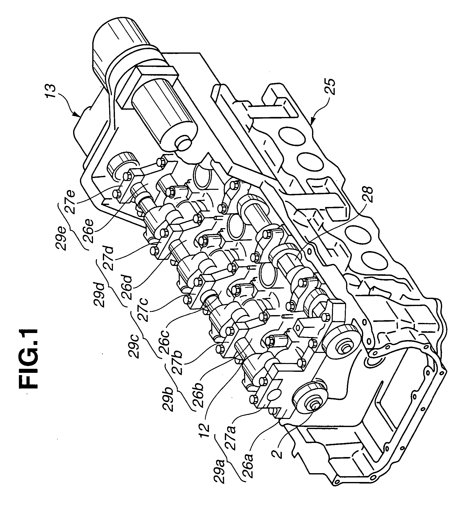
[0022]FIGS. 1-4 show a variable valve actuating system or apparatus according to the present invention. In this embodiment, the invention is applied to an inline four-cylinder engine. However, the present invention is also applicable to an internal combustion engine with other cylinder arrangement such as a V-type engine, and a six-cylinder or other multi-cylinder engine.
[0023] The variable valve actuating system, shown in FIGS. 1 and 2, for varying a valve lift characteristic of intake valves continuously includes, in combination, a lift and operation angle varying or control mechanism 1 capable of varying a intake valve lift quantity and an intake valve operation angle, and a phase varying or control mechanism 21 for advancing or retarding a center phase (phase with respect to crank angle (not shown)). In this example, an exhaust cam 28 is an ordinary direct drive type cam (with fixed lift and operation angle, and fixed lift center phase) to open and close an exhaust valve. Howeve...
second embodiment
[0059] In the second embodiment, the temperature of lubricating oil from lubricating oil supply pipe system 40 is not influenced by actuator 13, the temperature of bearing 29e nearest to actuator 13 can be further increased relatively. Thereby, this arrangement can further reduce the temperature unevenness of control shaft 12 in the longitudinal direction, further reduce variations in intake valve lift quantity among cylinders, and reduce variation in torque of the internal combustion engine.
[0060]FIG. 9 shows one practical example according to a third embodiment of the present invention. In the third embodiment, lubricating oil supply pipe 40 is arranged to differentiate the amounts of the lubricating oil supplied to five bearings 29 in accordance with the location of the bearing 29 through which the lubricating oil is supplied into hollow section 31 of control shaft 12, that is, the location of cam bracket 26 formed with oil hole 32.
[0061] When bearing 29 with oil hole 32 is loca...
third embodiment
[0063]FIG. 9 shows one practical example of lubricating oil supply system 40 according to the The oil supply pipe system 40 includes a longitudinal pipe extending along controls shaft 12 above control shaft 12, and the longitudinal pipe is formed with a plurality of outlet holes 42 for directing the lubricating oil to bearings 29, respectively. In this example, outlet holes 42 are not equal in size or diameter. The opening sizes of outlet holes 42 are so determined as to uniformize the temperature of control shaft 12 in the longitudinal direction. Alternatively, it is possible to employ a lubricating oil supply pipe system 45 shown in FIG. 10.
[0064] In lubricating oil supply system 40 shown in FIG. 9, the diameters of circular outlet holes 42 are increased in a stepwise manner from the left end to the right end of the pipe, so as to increase the amount of discharged lubricating oil from the left side to the right side.
[0065] In FIG. 10, arrows show spray or drop directions of the ...
PUM
 Abstract
Description
Claims
Application Information
 - R&D
- Intellectual Property
- Life Sciences
- Materials
- Tech Scout
- Unparalleled Data Quality
- Higher Quality Content
- 60% Fewer Hallucinations
Browse by: Latest US Patents, China's latest patents, Technical Efficacy Thesaurus, Application Domain, Technology Topic, Popular Technical Reports.
© 2025 PatSnap. All rights reserved.Legal|Privacy policy|Modern Slavery Act Transparency Statement|Sitemap|About US| Contact US: help@patsnap.com


