
Gas/liquid separation in water injection into hydrocarbon reservoir

a technology of hydrocarbon reservoir and gas/liquid separation, which is applied in the direction of liquid degasification, separation process, chemistry apparatus and process, etc., can solve the problems of reducing oxygen, reducing equipment, and reducing oxygen

Inactive Publication Date: 2005-06-09
SINGLE BUOY MOORINGS NC
View PDF4 Cites 11 Cited by
  • Summary
  • Abstract
  • Description
  • Claims
  • Application Information

AI Technical Summary

Benefits of technology

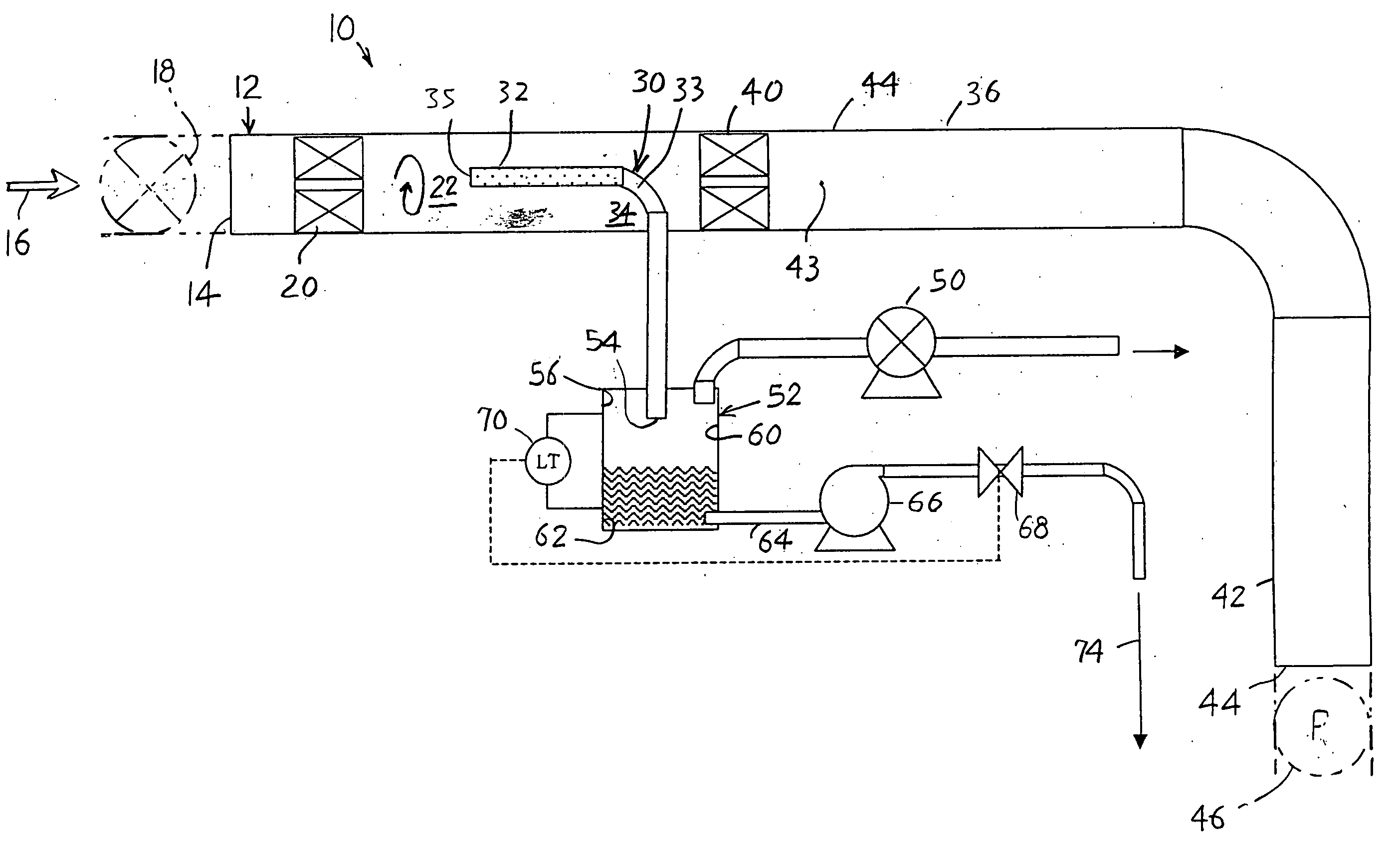
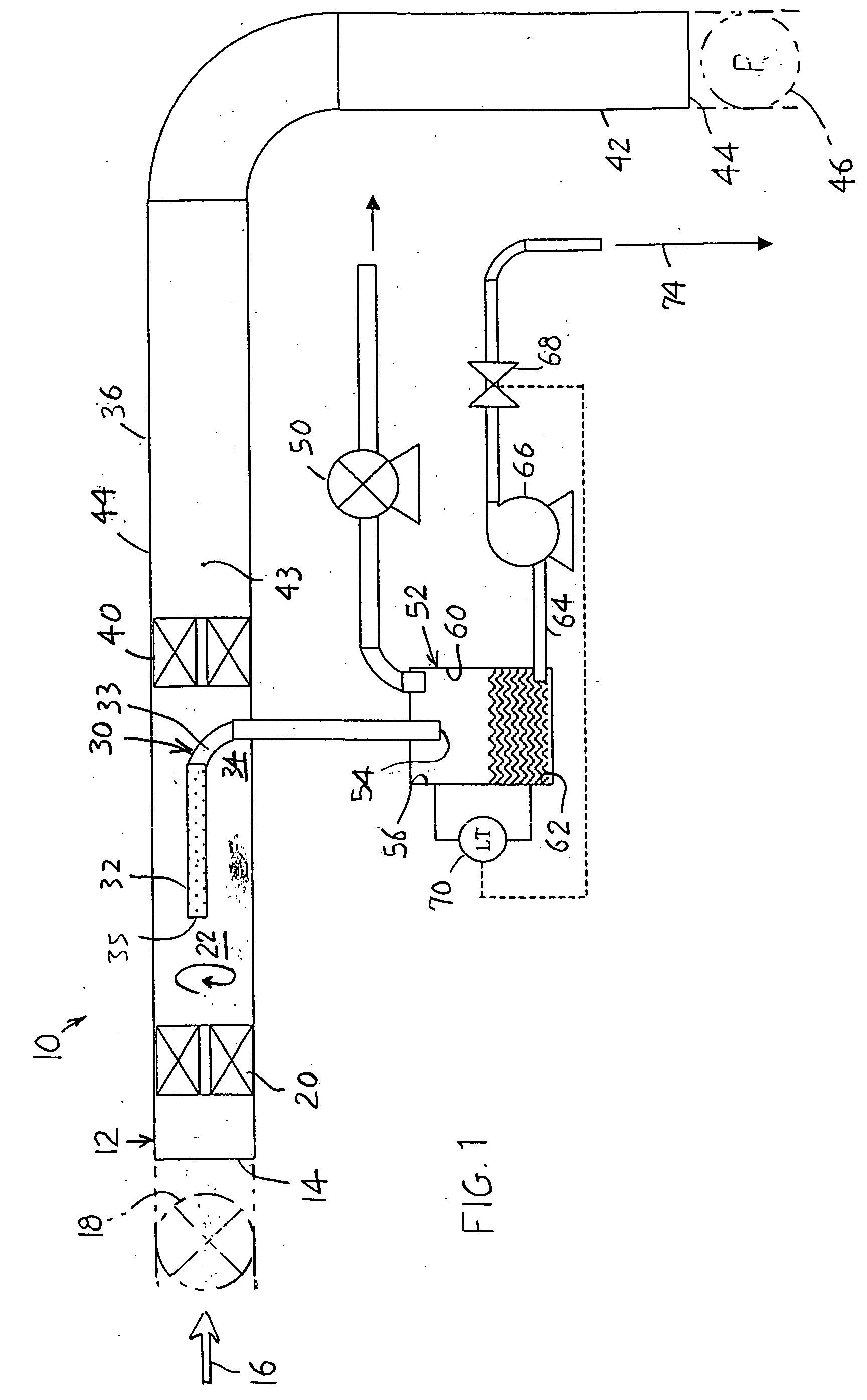
[0004] In accordance with one embodiment of the present invention, applicant provides an apparatus and method for separating gas from liquid, and for reducing oxygen in water that is to be injected into a hydrocarbon reservoir. A fluid stream which is a combination of water and dissolved gases, passes into a main conduit where its pressure is reduced to cause dissolved gases to break out of solution. The resulting mixture of water and gases is centrifuged to move gas to the center of the conduit and water to the periphery. A gas pipe inlet portion lies at the center of the water conduit at a location closely downstream of the centrifuge, to remove gases from the fluid and pass them through the gas pipe and a vacuum pump to the atmosphere.
[0005] The amount of oxygen in the water to be injected may be further reduced by injecting nitrogen into the fluid stream before the centrifuge separation, to cause nitrogen to be dissolved in the water and displace some of the other gases that include oxygen. When the water pressure is reduced, more gas breaks out of solution and the oxygen content is further reduced.

Problems solved by technology

Once the water is pumped to high pressurize for reservoir injection, oxygen in the water can cause rapid corrosion of many of the steels commonly used in the construction of the system.
The oxygen also feeds undesirable biological activity in the reservoir.
This equipment is comparatively large.

Method used


Image

  • Gas/liquid separation in water injection into hydrocarbon reservoir
  • Gas/liquid separation in water injection into hydrocarbon reservoir
  • Gas/liquid separation in water injection into hydrocarbon reservoir

Examples


Embodiment Construction

[0009]FIG. 1 illustrates a system 10 with a main conduit, or water conduit, 12 with an inlet 14 that receives fluid 16 that is water that may have been filtered and that has dissolved gases. In the example to be described, the water is sea water (water with dissolved salts) with dissolved gases that consist primarily of air (21% oxygen, 78% nitrogen, 1% argon and trace amounts of other gases). It is the oxygen, which corrodes steels used in the construction of the water injection system, and which results in undesirable biological activity in a hydrocarbon reservoir, that is to be removed from the sea water. Where the fluid consists primarily of water, it sometimes will be referred to herein simply as “water.”

[0010] The system of FIG. 1 applies a vacuum to water at the entrance 14. This can be accomplished by a valve 18 upstream of the conduit. The restriction in flow caused by the valve is adjustable to regulate water pressure downstream of the valve. The reduced water pressure res...


PUM

PropertyMeasurementUnit
vertical heightaaaaaaaaaa
pressureaaaaaaaaaa
lengthaaaaaaaaaa

Abstract

A stream of primarily water is treated to remove oxygen before injecting the water into an underground hydrocarbon reservoir. The pressure of water moving through a conduit (12) is reduced to a low level to maximize the dissolution of oxygen and other gases that are dissolved in the water. The resulting two phase mixture is separated by centrifugal action caused by rotating the water inside the conduit. The rotation is induced by flowing the water past fixed spin blades (20). The oxygen and any other gases are removed from the center of the conduit through a gas pipe (30) and eventually pass out of the system to the atmosphere via a vacuum pump (50). As an enhancement, nitrogen may be introduced upstream of the centrifuge. The nitrogen injection saturates the water-gas solution to improve the dissolution of oxygen from the low pressure water, and also improves the efficiency of the gas-liquid separation by adjusting the gas volume fraction downstream of the fixed spin blades (20) to an optimal proportion of the total flow.

Description

CROSS-REFERENCE [0001] Applicant claims priority from U.S. Provisional Application Ser. No. 60 / 526,677 filed 3 Dec. 2003.BACKGROUND OF THE INVENTION [0002] When hydrocarbons are produced from underground hydrocarbon reservoirs (which may also lie under a sea), the pressure and production rate tends to fall unless a fluid such as water is injected into the reservoir. Sea water is probably the most common injected fluid used in the production of hydrocarbons from undersea reservoirs, although water produced along with hydrocarbons from a reservoir may be reinjected. Sea water generally has about 10 ppm (parts per million) of dissolved oxygen. Once the water is pumped to high pressurize for reservoir injection, oxygen in the water can cause rapid corrosion of many of the steels commonly used in the construction of the system. The oxygen also feeds undesirable biological activity in the reservoir. As a result, it is common to reduce the amount of oxygen before it is pressurized and inje...

Claims


Application Information

Patent Timeline
Patent Type & Authority Applications(United States)
IPC IPC(8): B01D19/00C02F1/20
CPCC02F1/20B01D19/0057
Inventor JOYNSON, JEREMY DUNCAN STUARTZEE, DIRK JOHAN VAN DER
Owner SINGLE BUOY MOORINGS NC
Learn More