
Vehicle seat with dual independently adjustable supports

Inactive Publication Date: 2005-06-02
ROBINSON GARRY
View PDF17 Cites 16 Cited by
  • Summary
  • Abstract
  • Description
  • Claims
  • Application Information

AI Technical Summary

Benefits of technology

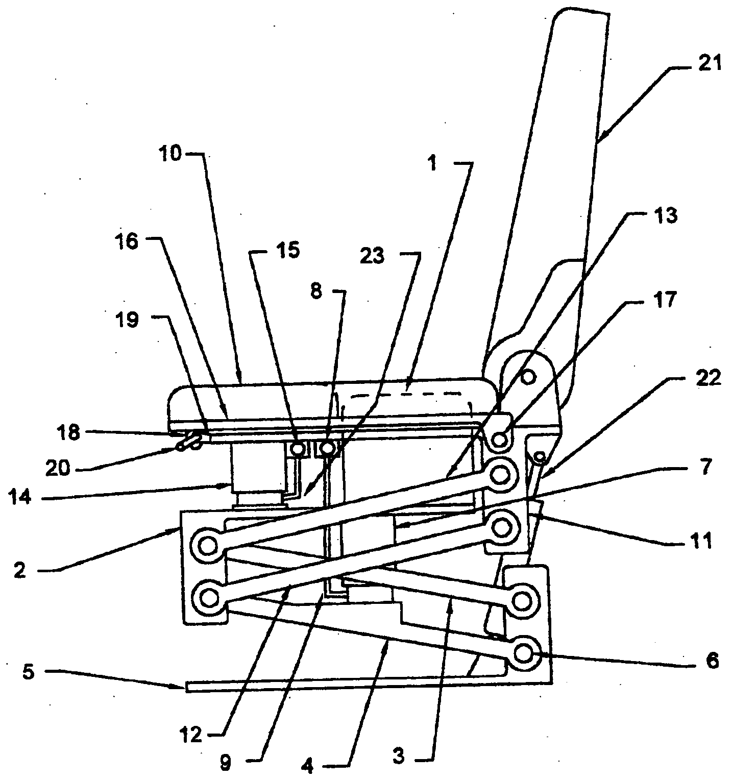
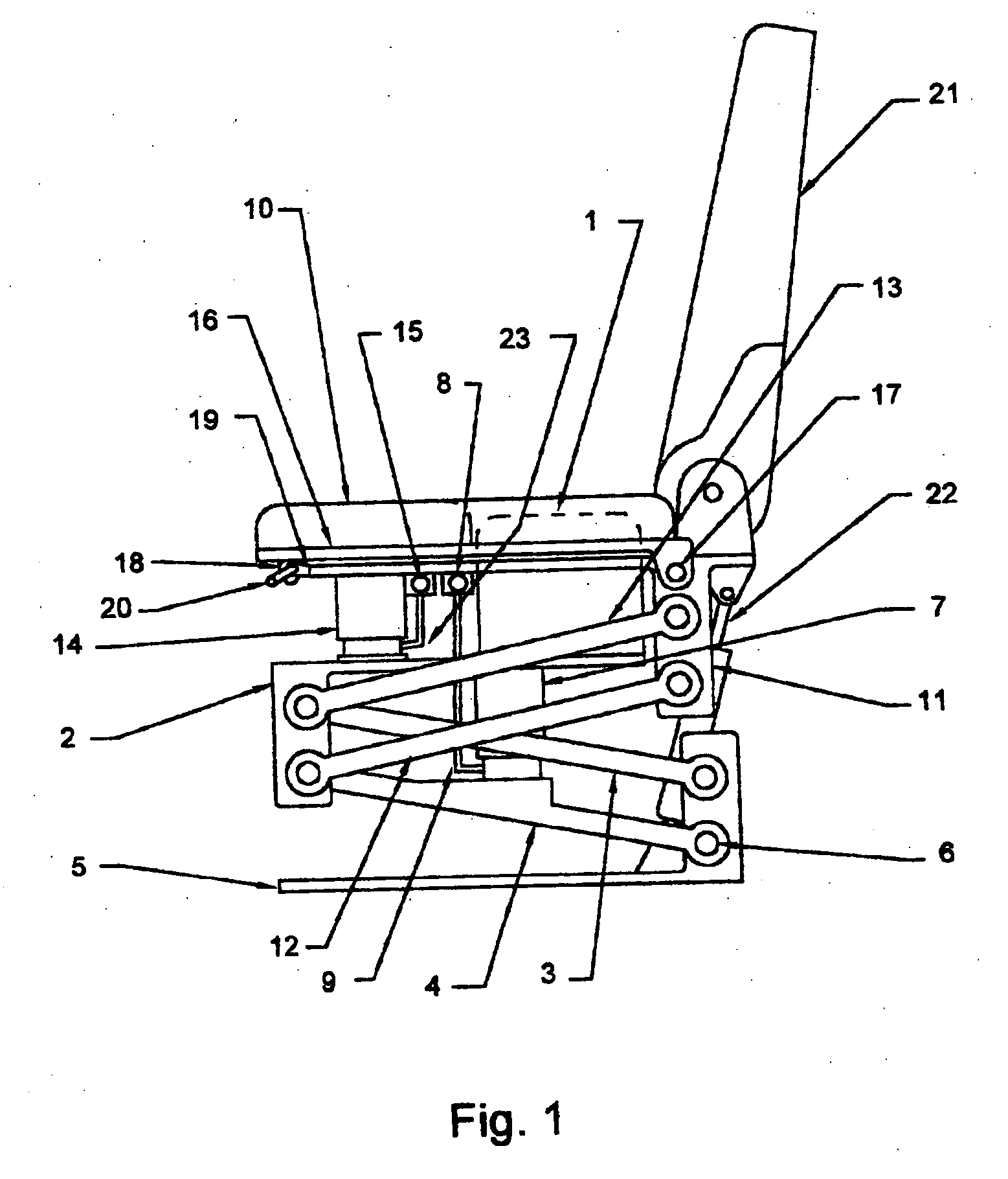
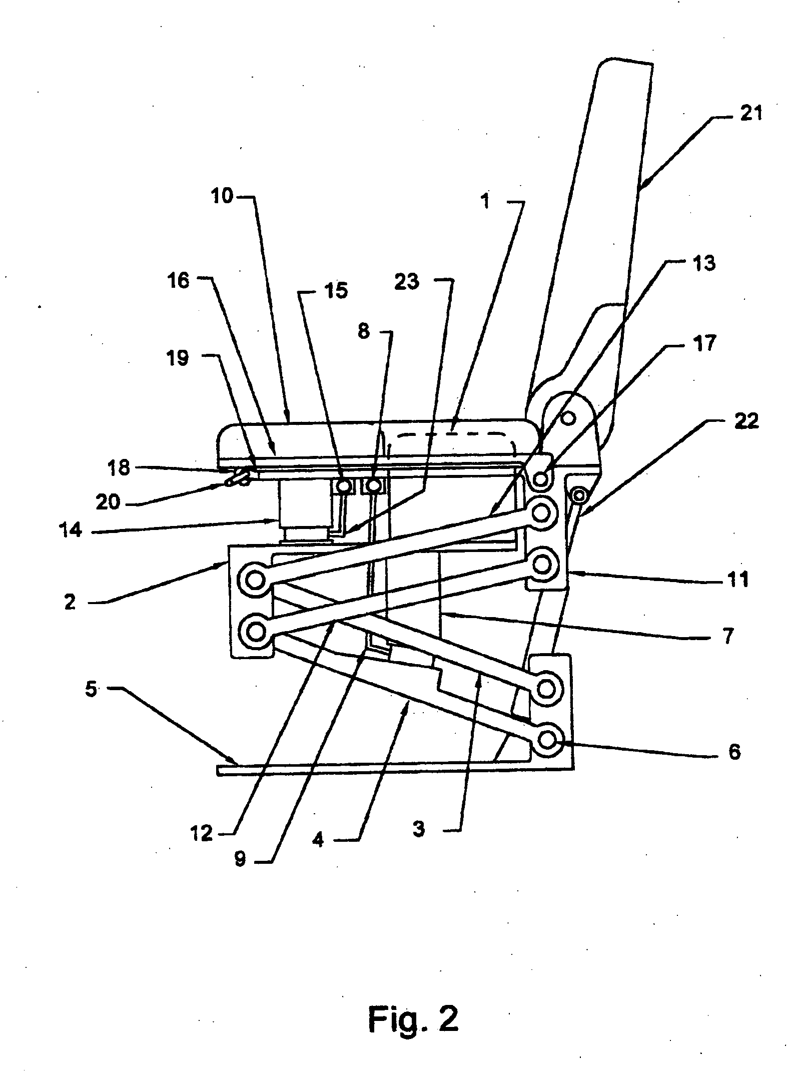
[0004] The apparatus of the present invention constitutes an improvement over the prior art by permitting the occupant of the seat to adjust the pressure distribution of the seat against the occupant's body parts from time to time, while maintaining the soft ride characteristics of a pivoted linkage type of seat. In a preferred embodiment of the present invention, hereinafter alternatively referred to as a “dual ride seat”, an inner seat including its cushion is mounted on a first sub-base supported by a first air actuator, and retained laterally by a lower parallelogram linkage configured so that by adding air into the first air actuator, the inner seat including its cushion and the outer seat including its cushion are caused to rise approximately vertically with respect to the vehicle floor. The pressure of the air in the first air actuator is adjusted manually to balance the weight of the occupant plus the two cushion assemblies at a ride height of the occupant's choosing. The inner seat and cushion is shaped and positioned to support the pelvic area directly below the base of the spine of a person sitting on the seat. An outer seat and its cushion is mounted on a second sub-base supported by a second air actuator, and retained laterally by an upper parallelogram linkage configured so that by adding air into the second air actuator, the outer seat and cushion is caused to rise approximately vertically with respect to the inner seat and cushion. The pressure of the air in the second air actuator is adjusted manually to change the amount of the occupant's weight supported by the outer seat and its cushion assembly. The outer seat and its cushion is shaped and positioned to support the backside of the thighs and the outer areas of the buttocks of the occupant. By manually adjusting the ride height of the outer cushion with respect to the inner cushion, the occupant can change the pressure distribution from completely supported by the inner cushion against the pelvis and consequently directly through the base of the spine, to completely supported by the thighs and outer buttock areas and indirectly to the spine through the hips.
[0005] When the body is supported solely by the outer cushion, the weight of the legs and lower torso is taken directly through the seat, thus reducing the load transmitted through the pelvis and the lower spine, and the upper body weight is supported in a more naturally balanced manner through the hips. When the body is supported solely by the outer cushion, the effective spring rate of the seat system is reduced to approximately one half of that of a single seat system, due to the arrangement of two air actuators acting in tandem. A damping device such as a hydraulic shock absorber may be connected between the base and either of the seat sub-bases so as to dampen repetitive oscillations of the seat cushions in the vertical direction. The provision for independent height adjustment of the outer cushion with respect to the inner cushion from time to time, permits the occupant to re-distribute the seat pressure so as to allow blood circulation to be maintained more properly, and to vary the load pattern in the joints and in the lower vertebrae. Furthermore, the outer cushion may be mounted on a pivoted plate with an adjusting means to vary the amount of support provided to the lower thighs.
[0006] The present invention may thus offer the following advantages over prior art:

Problems solved by technology

Operators of trucks and off-highway mobile equipment are required to spend many hours each working day subjected to continual bouncing and vibration, while in a sitting position, resulting in a high incidence of related injuries such as chronic lower back pain and circulatory deficiencies among such workers.
Such seats could offer relief from fatigue caused by continual seat pressure and vibration, but they do not address the absorption of large impacts related to vehicle operation on bumpy terrain and highways.

Method used


Image

  • Vehicle seat with dual independently adjustable supports
  • Vehicle seat with dual independently adjustable supports
  • Vehicle seat with dual independently adjustable supports

Examples


Embodiment Construction

[0028] As best seen in FIGS. 1, 2 and 3, according to a preferred embodiment of the present invention, the inner seat cushion 1, shown in partially dotted outline in FIGS. 1 and 2, is mounted on a first sub-base 2. First sub-base 2 is suspended by being pivotally mounted to two pairs of lower parallel arms 3 and 4, wherein the pair of lower parallel arms 3 comprise a pair of arms of which only the near arm is visible as drawn, and wherein lower parallel arms 4 comprise a pair of arms of which only the near arm is visible as drawn, and wherein the lower two pair of parallel arms 3 and 4 are pivotally attached to a fixed base 5. Pins 6 permit free rotation of the lower parallel arms 3 and 4 in a vertical plane only, perpendicular to the pin 6 axis. A first air actuator 7 is mounted between the first sub-base 2 and the lower pair of parallel arms 4 so that air pressure, when admitted to the first air actuator 7 causes the first sub-base 2 to be lifted with respect to the base 5 as the ...


PUM


Abstract

A vehicle seat, which provides an enhanced level of comfort, by means of dual independently supported seat cushions is disclosed. The apparatus comprises an inner seat cushion and an outer seat cushion, each of which is independently supported by a compressed air pneumatic device to control vertical movement, and by parallelogram linkages control lateral movement, and allow for vertical transition of the seats while maintaining them horizontal. The occupant of this vehicle seat can independently adjust the distribution of body weight shared by the inner seat cushion and the outer seat cushion from time to time, in order to change the pressure pattern against body parts and to provide optimum ergonomic seating posture. Furthermore, by adjusting the air supply, the occupant can increase or decrease the seat's effective spring rate, thus controlling the ride height and the seat's compliance for travel on both rough terrain and smooth roadways.

Description

FIELD OF THE INVENTION [0001] The present invention relates to a vehicle seat constructed with two separate seat cushions, wherein each seat cushion is supported in a generally vertical direction by compressed air, and each cushion is supported laterally in both the fore and aft direction, and in the side to side direction, by mechanical means. One seat cushion, hereinafter referred to as the “inner seat cushion”, is shaped and positioned to support the occupant's pelvic area directly below the base of the spine. The other seat cushion, hereinafter referred to as the “outer seat cushion”, is shaped and positioned to support the backside of the occupant's thighs and the outer areas of the buttocks. A control valve in the air supply line to each cushion permits the occupant to regulate the height of each cushion independently from the other cushion. Furthermore, the outer cushion may be mounted on an adjustable sub-structure attached to the outer cushion support means so as to permit ...

Claims


Application Information

Patent Timeline
IPC IPC(8): B60N2/52
CPCB60N2/501B60N2/502Y10S297/03B60N2/507B60N2/525B60N2/505
Inventor ROBINSON, GARRY
Owner ROBINSON GARRY
Learn More