Device and method for inspecting inside of underground pipe line and method of inspecting concrete on inside of underground pipe line for deterioration
- Summary
- Abstract
- Description
- Claims
- Application Information
AI Technical Summary
Benefits of technology
Problems solved by technology
Method used
Image
Examples
first embodiment
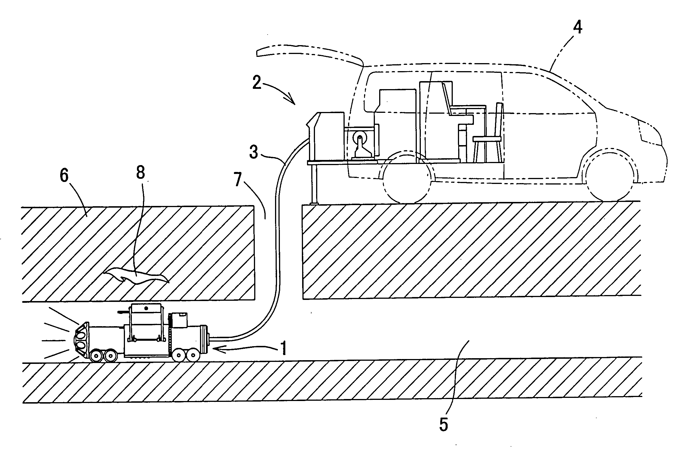
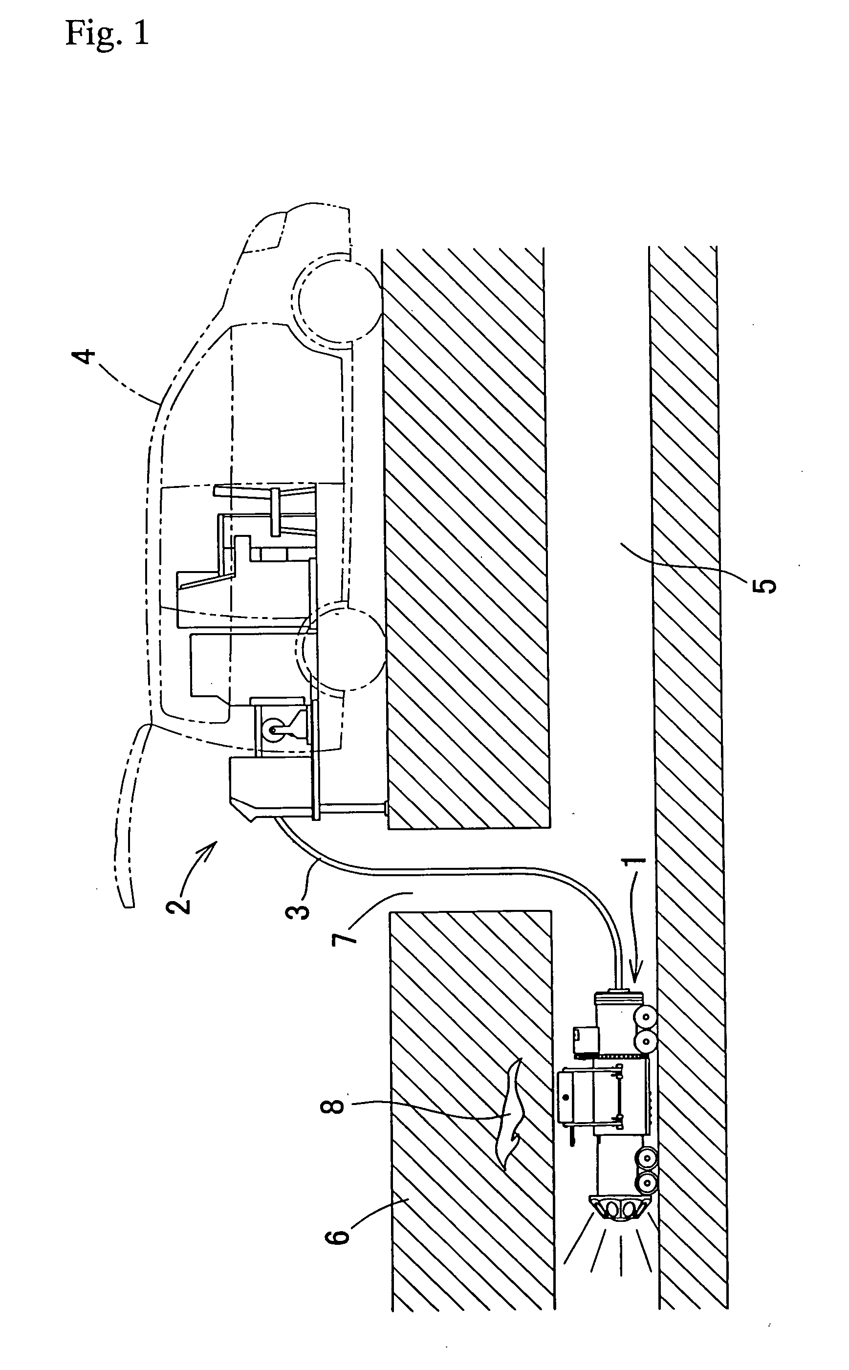
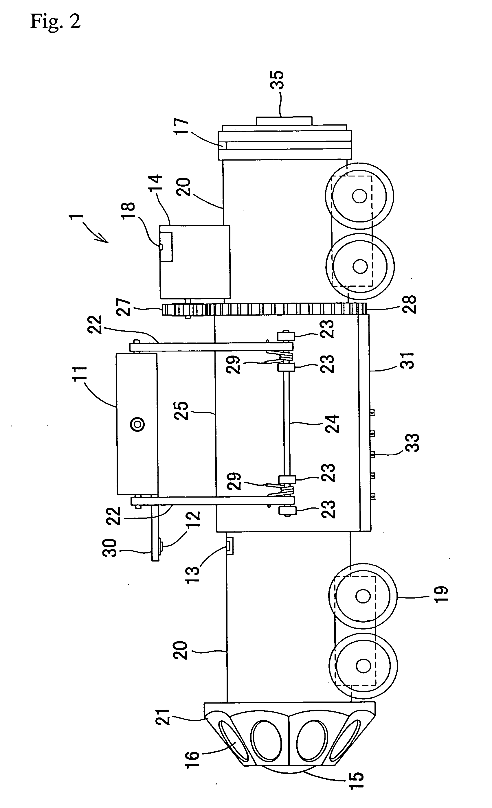
[0062] Further, the signal outputted from the rotating radar antenna 11 has to be transmitted to the on-ground control unit 2. Here, a slip ring is provided on the surface of the inner sleeve 26, and a brush 33 made from carbon is fit into a brush fitting orifice 32 of the brush mounting portion 31 provided at the outer sleeve 25, so that the brush is brought into contact with the slip ring. A wire for the signal outputted from the radar antenna 11 is connected to the brush 33. Further, the signal wire which is conductively linked to the slip ring on the surface of the inner sleeve 26 is connected to the on-ground control unit 2 via a connector 35 for a connecting cable. In the first embodiment, the above-described mechanism is used to pick up the signals outputted from the rotating radar antenna 11.
[0063] The control unit 2 receives and analyzes the signals outputted from the rotating radar antenna 11, forms a two-dimensional radar image with a traveling direction of the pipe line ...
second embodiment
[0073] With the above-described underground pipe line internal inspection device of the second embodiment, a concrete deterioration diagnostic reagent which changes the color of the surface to which it has adhered according to the presence or absence of concrete deterioration is sprayed on the inner peripheral surface of concrete in the underground pipe line and the results are picked up with a fisheye lens camera. Therefore, a decision relating to the presence or absence of concrete deterioration in the line can be made based on the picked-up images.
[0074] Further, the above-described underground pipe line internal inspection device of the second embodiment, similarly to the underground pipe line internal inspection device of the first embodiment, has a radar for cavity inspection, a gyro, a laser sensor, and a function of establishing the correspondence between the radar image and the expanded image, or an infrared encoder. Therefore, it demonstrates functions and effects identica...
third embodiment
[0076] In FIGS. 9 to 12, the parallel link mechanism 60 for raising and lowering the antenna in the pipe line internal self-propelled vehicle 59 of the device for inspecting the inside of an underground pipe line of the third embodiment has the following structure.
[0077] A rectangular antenna support frame 62 is so disposed that the short side thereof is aligned in the front-back direction along the traveling direction of the pipe line internal self-propelled vehicle 59 and comprises four guide bars 63 extended with downward inclination forward or backward at the front end or rear end of the long side of the antenna support frame 62. The inner side surfaces of the long sides of the antenna support frame 62 and guide bars 63 are inclined so as to open with upward and outward inclination with respect to the traveling direction of the pipe line internal self-propelled vehicle 59. Further, guide rollers 65 are rotatably mounted on the outer side surfaces of the long sides of the antenna...
PUM
 Abstract
Description
Claims
Application Information
 - R&D
- Intellectual Property
- Life Sciences
- Materials
- Tech Scout
- Unparalleled Data Quality
- Higher Quality Content
- 60% Fewer Hallucinations
Browse by: Latest US Patents, China's latest patents, Technical Efficacy Thesaurus, Application Domain, Technology Topic, Popular Technical Reports.
© 2025 PatSnap. All rights reserved.Legal|Privacy policy|Modern Slavery Act Transparency Statement|Sitemap|About US| Contact US: help@patsnap.com


