
Flexible rate split method for MIMO transmission

a rate split and transmission method technology, applied in the field of multi-input/multi-output (imo) communication system, can solve problems such as and achieve the effect of inability to maximize ra

Inactive Publication Date: 2005-05-26
NOKIA CORP
View PDF19 Cites 91 Cited by
  • Summary
  • Abstract
  • Description
  • Claims
  • Application Information

AI Technical Summary

Benefits of technology

"The present invention improves upon previous methods by encoding subpackets or streams across both space and time. The method involves determining the quality of a first channel, dividing the packet into two subpackets with different sizes, and transmitting them over different channels. The subpackets are encoded using a single encoder of length N, and may use eigenvectors to transmit them over more than one channel at a power determined by the feedback circuit. The invention also includes a transmitter with an encoder, channel feedback circuit, demultiplexer, amplifier, and antennas. The use of eigenvectors allows for maximization of transmission rates, while the feedback circuit ensures efficient use of channels. The technical effects of the invention include improved transmission efficiency and better utilization of channel capacity."

Problems solved by technology

In practice, the rate cannot be maximized because many air interface standards, including cdma2000, release C, allow only certain packet sizes to be transmitted.

Method used


Image

  • Flexible rate split method for MIMO transmission
  • Flexible rate split method for MIMO transmission
  • Flexible rate split method for MIMO transmission

Examples


Embodiment Construction

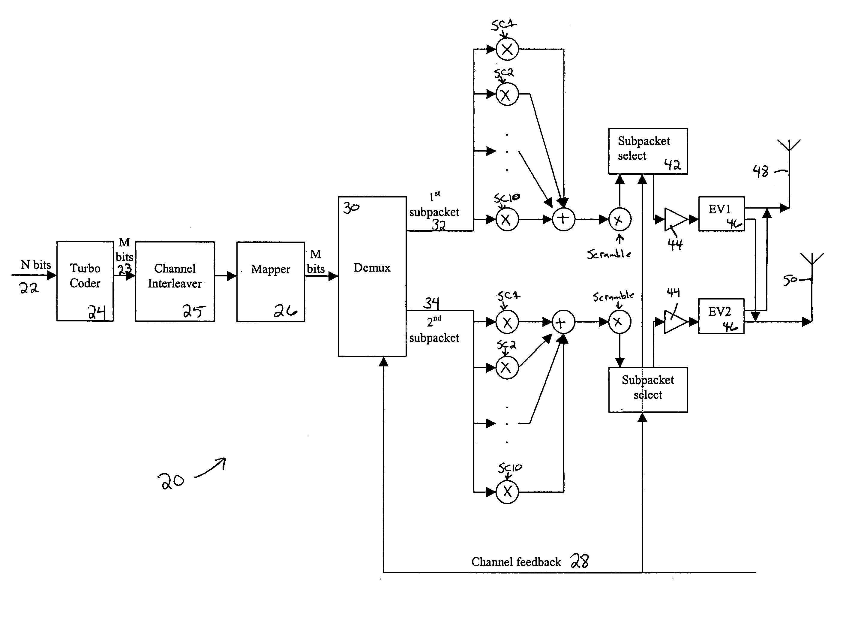
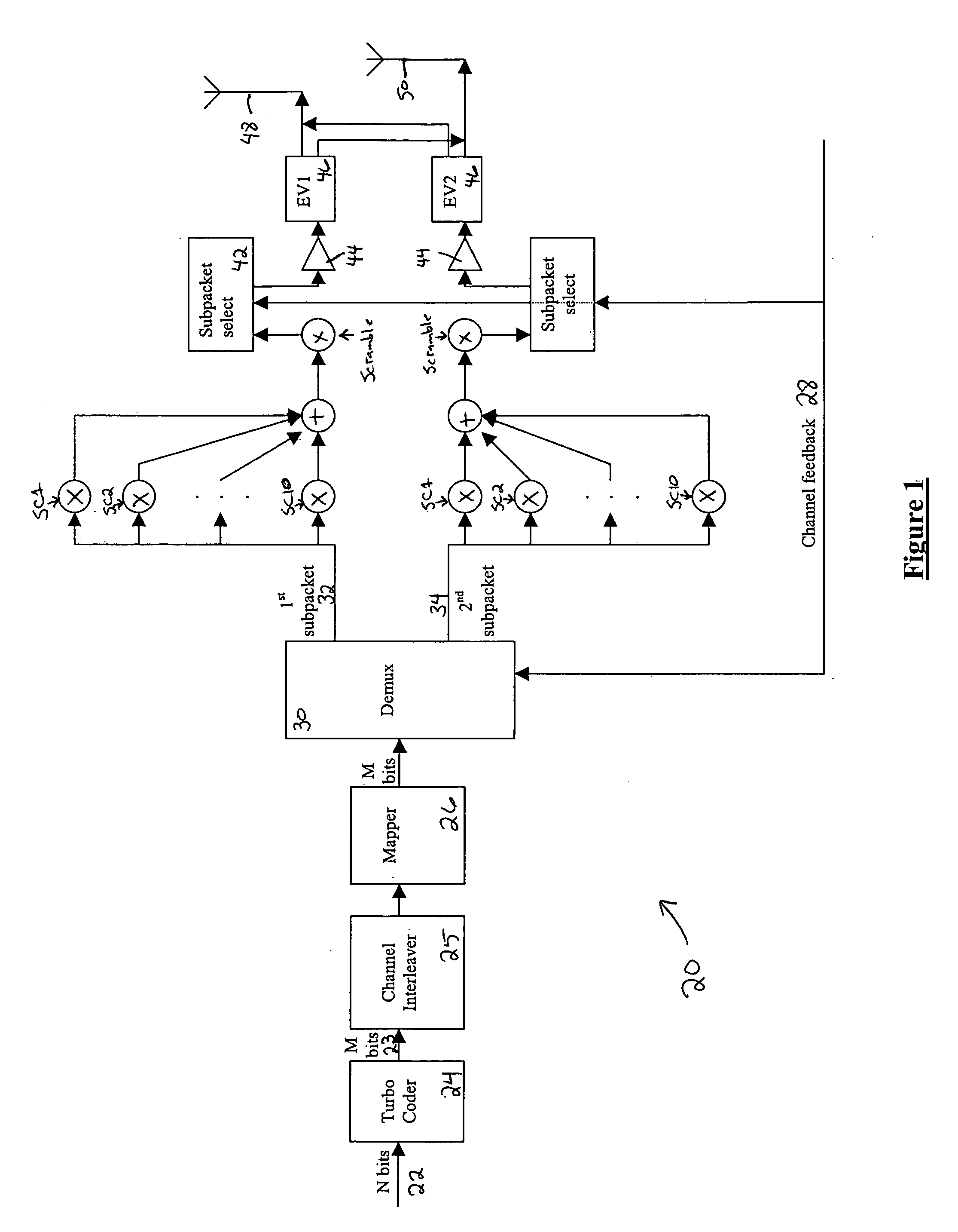
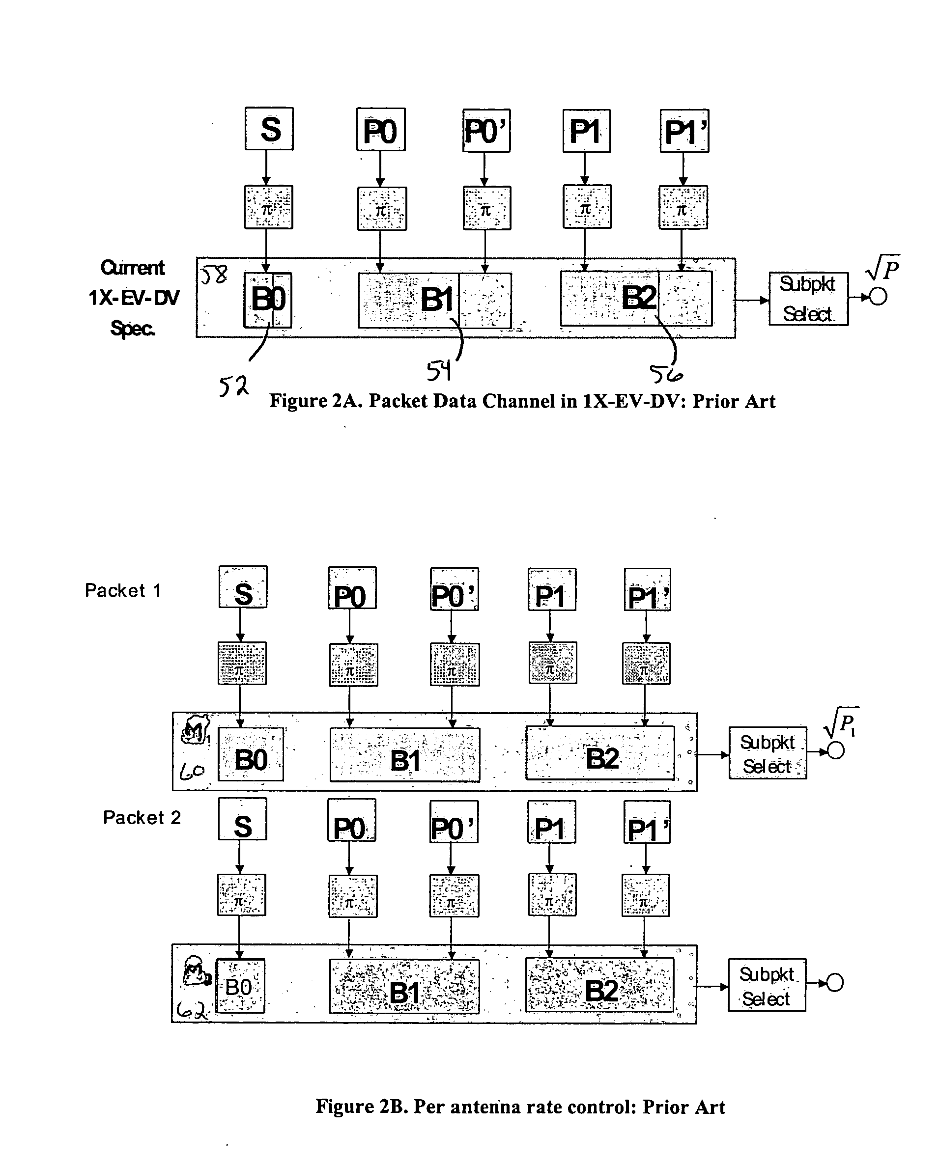
[0017] The present invention improves upon the prior art by encoding the streams across both space and time, and dividing the systematic bits among streams based on knowledge of the channel parameters. This knowledge may come from a receiver over an uplink channel, from measurement of the uplink channel by the receiver, or both. Other sources of channel quality measurement may also be employed. The present invention is compatible with the packet data channel (F-PDCH) of the 1×EV-DV standard, commonly known as cdma2000 release C, and described below. For a 1×EV-DV application, the uplink channel may be the reverse channel quality indicator channel (R-CQICH) or the reverse acknowledgement channel (R-ACKCH).

[0018] CDMA, or code-division multiple access, is a highly efficient use of radio spectrum based on a spread spectrum technique by which a narrow band voice or data signal is multiplied over a relatively wide band by a spreading code, generally termed a Walsh-Hadamard code or a Wal...


PUM


Abstract

A method for transmitting a packet of N input bits includes encoding all of the N bits as a single entity, such as with an interleaver of length N within a turbo coder, outputting M encoded bits, channel interleaving the M bits, splitting the M encoded bits into a parallel first and second portion, and transmitting them over separate channels to achieve spatial diversity. The size of the first and second portion is determined based on a closed feedback loop that provides some knowledge of the channel, preferably a measure of channel capacity. The feedback loop may also provide channel knowledge to a subpacket selector associated with each transmit antenna, which determines an appropriate rate for that channel and selects subpackets to fill a transmission packet for that channel. The subpacket selectors choose a subpacket of systematic bits and fill the remaining transmission packet size with subpackets of parity bits. Eigenvectors may be employed to transmit each transmission packet over more than one channel with a power disparity between the channels. A transmitter according to the present invention is also described.

Description

FIELD OF THE INVENTION [0001] The present invention relates to a multiple input / multiple output (IMO) communication system in which the transmitter has some knowledge of the channel parameters over which it transmits. It is particularly directed to dividing bits of an input packet into two streams based on the channel parameters, and transmitting those streams using the multiple antennas. BACKGROUND [0002] Modulated wireless signals from a transmitter reach a receiver by a number of propagation paths. The characteristics of each path vary over time and between one another due to factors such as fading, multipath, and different signal to interference and noise ratio (SINR). Multiple transmit and / or receive antennas may be used to provide diversity that insures against adverse effects on any of these paths, because the likelihood of correctly receiving a transmission increases with the number of transmit antennas so long as one propagation path is not merely a linear combination of th...

Claims


Application Information

Patent Timeline
Patent Type & Authority Applications(United States)
IPC IPC(8): H04B7/00H04B7/04H04B7/06H04L
CPCH04B7/0417H04B7/0443H04B7/0632H04B7/0669H04B7/0697H04L1/0002H04B7/0465H04L1/0033H04L1/0041H04L1/0065H04L1/0071H04L1/06H04L1/0656H04L1/0007H04J3/16H04B7/0619
Inventor RAGHOTHAMAN, BALAJIZHANG, JIANZHONG
Owner NOKIA CORP
Learn More