
Inkjet printer and inkjet printing method

a technology of inkjet printer and inkjet printing, which is applied in the direction of printing, other printing apparatus, etc., can solve the problems of user burden, user difficulty in adjusting light transmittance,

Inactive Publication Date: 2019-08-06
ROLAND DG CORP
View PDF13 Cites 0 Cited by
  • Summary
  • Abstract
  • Description
  • Claims
  • Application Information

AI Technical Summary

Benefits of technology

[0006]Preferred embodiments of the present invention provide photocurable-type inkjet printers capable of flexibly adjusting the light transmittance or the light blocking property of a surface on which printing is to be performed by a technique different from a conventional technique.
[0008]The inkjet printer having the above-described structure forms the matte clear ink layer by use of the clear ink on the recording medium before performing printing by use of the color ink. The matte clear ink layer refracts and scatters light incident thereon. Therefore, the inkjet printer having the above-described structure varies the light transmittance or the light blocking property of a surface on the printing is to be performed because of the effect provided by the refraction and scattering of light. For example, when the degree of light refraction by the clear ink layer is increased, the light transmittance of the surface on which the printing is to be performed is decreased. This increases the visual recognizability of the printed color image. As a result, the color tone of the printed color image is made clear. In the case where the degree of light refraction by the clear ink layer is varied, a wider diversity of representations is realized as compared with a conventional case where the underlying layer is the white ink layer. Thus, the degree of freedom of design is improved.

Problems solved by technology

Therefore, it is difficult for a user to adjust the light transmittance and the light blocking property of the white ink layer 50W.
Such requirements impose a burden on a user.

Method used


Image

  • Inkjet printer and inkjet printing method
  • Inkjet printer and inkjet printing method
  • Inkjet printer and inkjet printing method

Examples


Embodiment Construction

[0020]Hereinafter, preferred embodiments according to the present invention will be described with reference to the drawings. The preferred embodiments do not limit the present invention in any way. Components or sites having the same function will bear the same reference signs, and overlapping descriptions will be omitted or simplified when necessary.

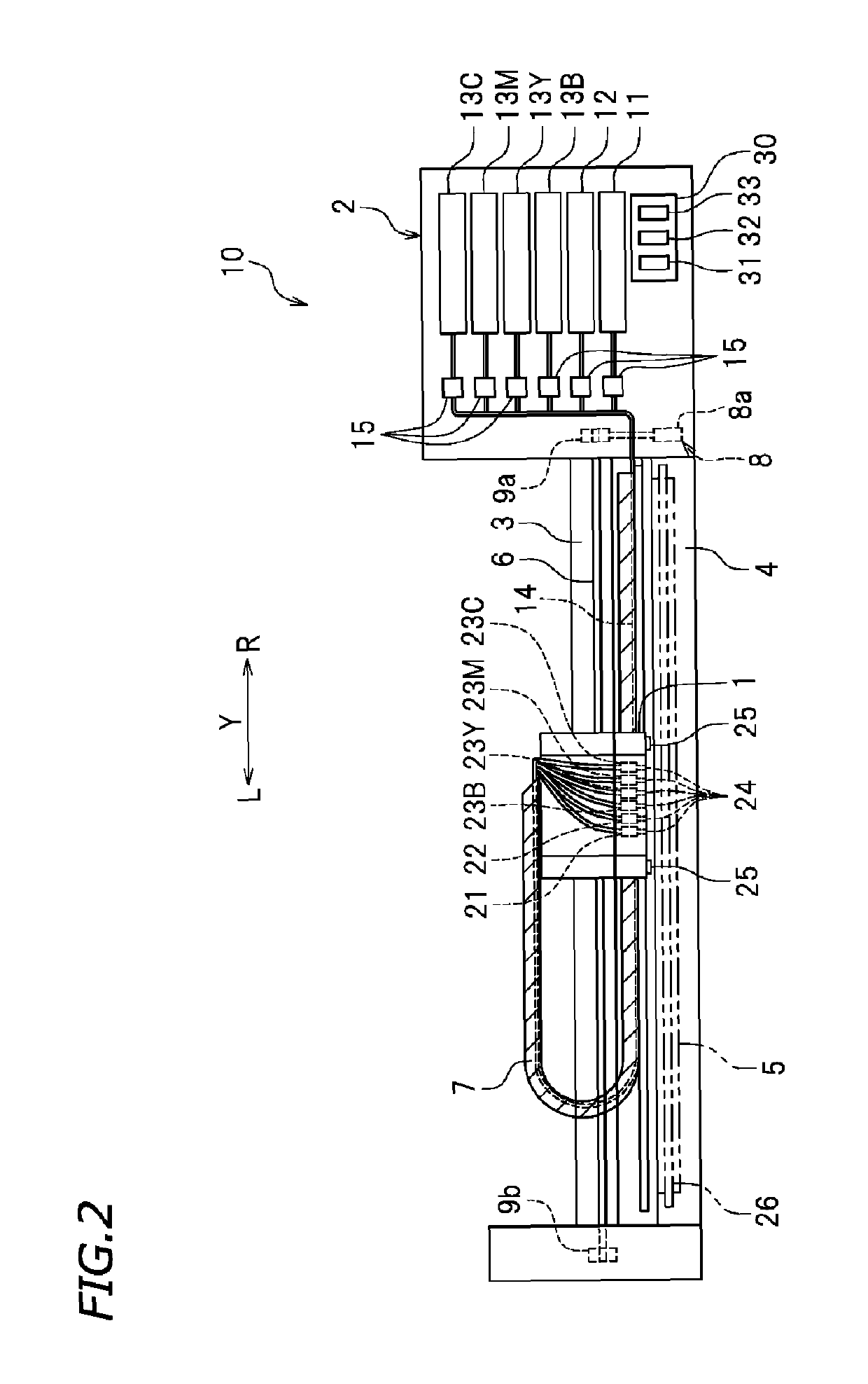
[0021]First, an inkjet printer 10 will be described. FIG. 1 is a perspective view of a large inkjet printer (hereinafter, may be referred to simply as a “printer”) according to a preferred embodiment of the present invention. FIG. 2 is a front view showing a main portion of the printer 10. In the drawings, letter X represents a sub scanning direction and a front-rear direction. In the drawings, letters F and Rr respectively represent “front” and “rear”. In the drawings, letter Y represents a main scanning direction and a left-right direction. In the drawings, letters L and R respectively represent “left” and “right”. These directions a...


PUM


Abstract

A printer includes a clear ink tank, a color ink tank, a clear ink injection head, a color ink injection head, a light source, and a controller. The controller includes a matte printing controller structured or programmed to cause clear ink to be injected from the clear ink injection head and to be irradiated by the light source to form a matte clear ink layer on a recording medium; and a color printing controller structured or programmed to cause color ink to be injected from the color ink injection head to form a color ink layer on the clear ink layer.

Description

CROSS REFERENCE TO RELATED APPLICATIONS[0001]This application claims the benefit of priority to Japanese Patent Application No. 2016-216180 filed on Nov. 4, 2016. The entire contents of this application are hereby incorporated herein by reference.BACKGROUND OF THE INVENTION1. Field of the Invention[0002]The present invention relates to an inkjet printer using photocurable ink and an inkjet printing method.2. Description of the Related Art[0003]Conventionally, a photocurable-type inkjet printer using photocurable ink to print an image or the like on a recording medium is known. This type of printer includes an inkjet head injecting photocurable ink toward the recording medium, and an irradiation device irradiating the recording medium with light. The photocurable ink injected from the inkjet head arrives at the recording medium. The photocurable ink on the recording medium is irradiated with light from the irradiation device. As a result, the photocurable ink is cured and adheres to ...

Claims


Application Information

Patent Timeline
Patent Type & Authority Patents(United States)
IPC IPC(8): B41J2/21B41J11/00B41J2/045
CPCB41J2/2114B41J11/002B41J2/2117B41J2/04531B41J11/00218B41J11/00214G06K15/023
Inventor KATSUNO, YUKINORITAKAHASHI, KOJIOISHI, KEIKOYAGI, TAKESHISAITO, SATOSHI
Owner ROLAND DG CORP
Learn More