
Planarization of an image detector device for improved spectral response

a detector device and image technology, applied in the direction of diodes, solid-state devices, electrical devices, etc., can solve the problems of reducing the quantum efficiency of the sensor, no reason to perform this additional step of planarization, and complicated production process, so as to improve the spectral response and quantum efficiency of the detector devi

Inactive Publication Date: 2005-05-26
CYPRESS SEMICONDUCTOR CORP (BELGIUM) BVBA
View PDF2 Cites 20 Cited by
  • Summary
  • Abstract
  • Description
  • Claims
  • Application Information

AI Technical Summary

Benefits of technology

[0010] It is an object of the present invention to reduce or overcome the above mentioned lensing problem in image sensor devices. It is a further object of the present invention to improve the spectral response and quantum efficiency of a detector device preferably without relying on expensive and difficult manufacturing processes.
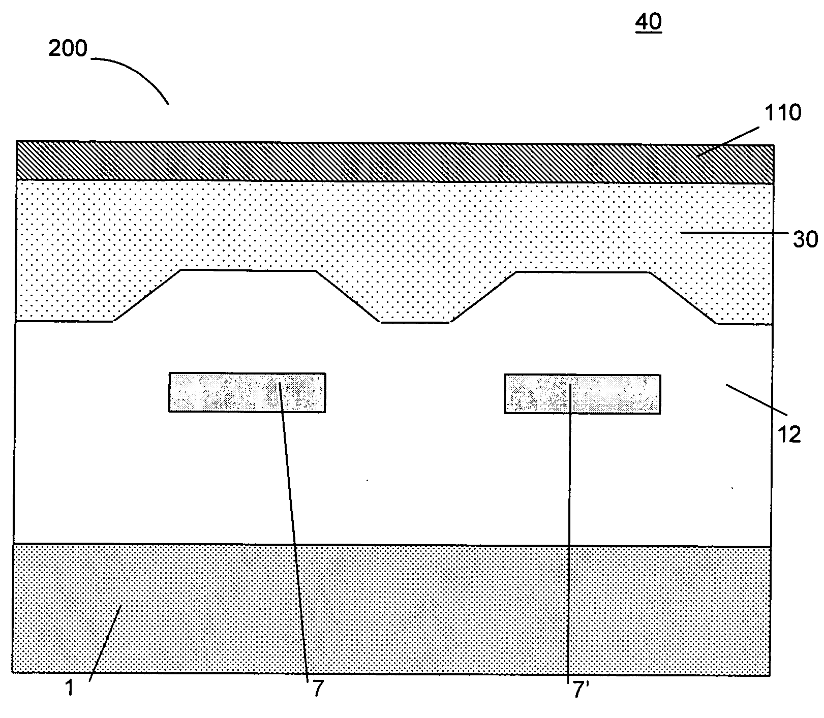
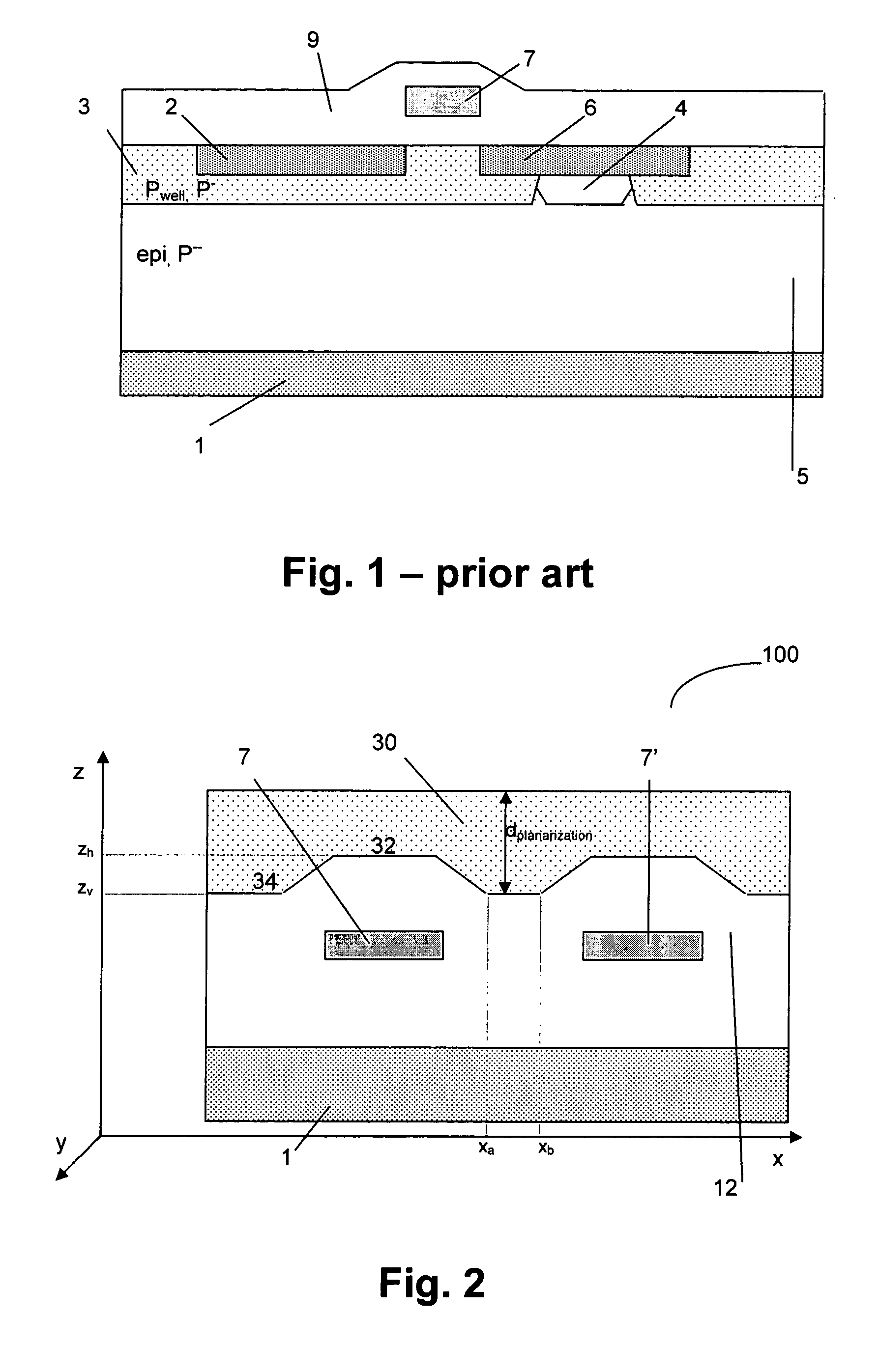
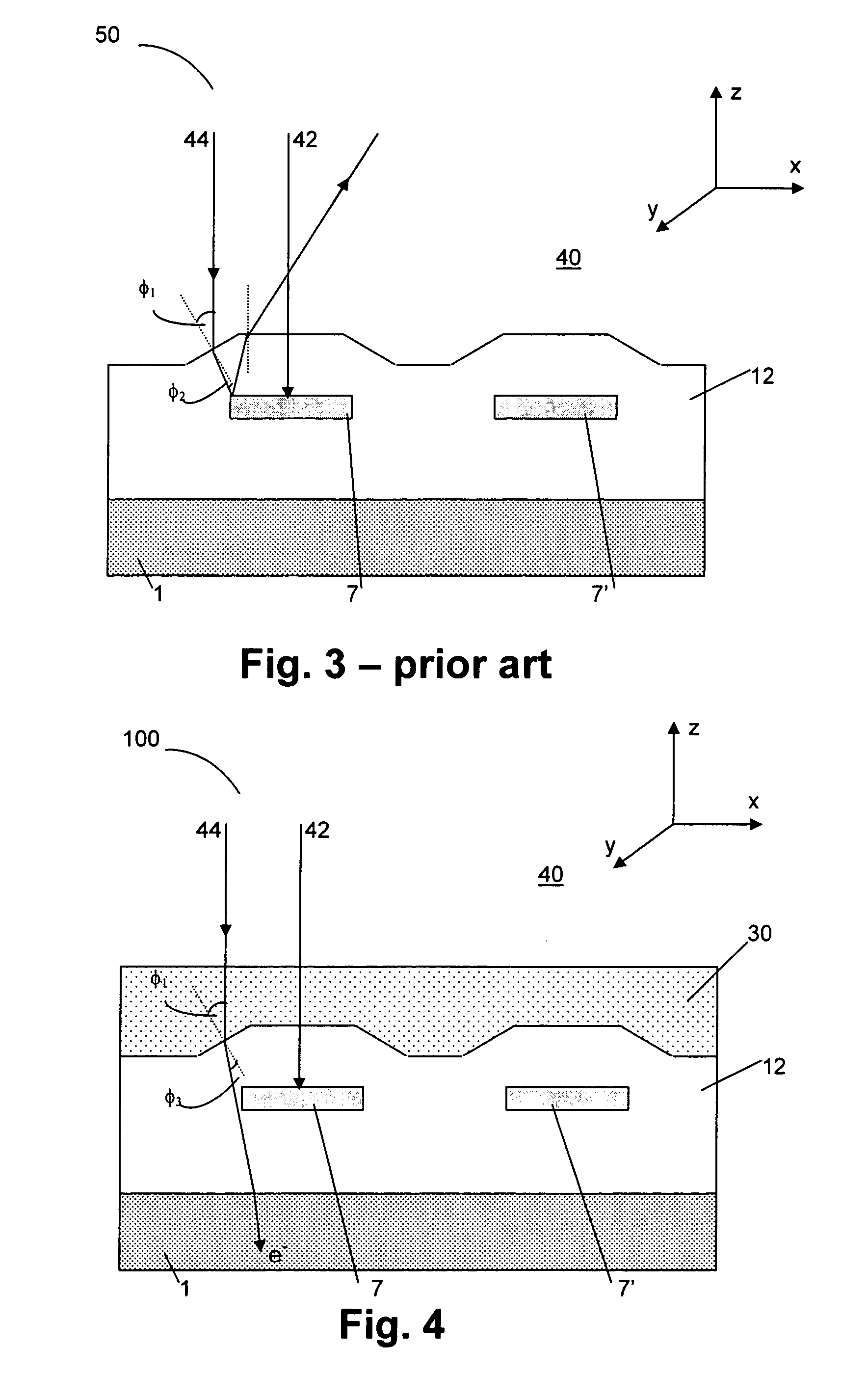
[0011] The above objectives are accomplished by a monochrome image sensor device according to the present invention. The monochrome image sensor device comprises a substrate and a pixel structure. The monochrome image sensor device furthermore comprises a planarisation layer on top of the pixel structure, whereby the planarisation layer at the same time is an anti reflective coating. This has as advantage that lensing effects by a non-flat surface of the pixel structure are substantially reduced or even avoided. The thickness of said planarisation layer and the refractive index of the layer can be optimized to also act as an anti-reflection medium for at least one region of the image sensor device. In this way, the anti-reflection properties are further improved. However, also if the thickness of the planarisation layer is not optimized, it acts as an anti reflective coating. The planarisation layer can be a polymer, preferably a photoresist. The pixel structure in the monochrome image sensor device preferably is a MOS-based pixel structure. It can be either an active pixel or a passive pixel structure.
[0015] The present invention also provides a method for making a monochrome image sensor device comprising the steps of providing a substrate, applying a pixel structure on or in the substrate and providing a planarisation layer on top of the pixel structure. This planarisation layer on top of the pixel structure avoids lensing effects by a non-flat surface of the pixel structure. Applying the pixel structure may comprise the use of MOS-based processing technology. The planarisation layer can be formed using any method which allows to create a flat surface. The planarisation layer may be made using spin coating or dip coating. The planarisation layer may be made by providing a stack of films. This stack of films may have gradually changing refractive indexes. The method of making the monochrome image sensor may further comprise depositing a real anti-reflective coating on top of the planarisation layer.
[0016] The invention furthermore also provides a method for improving light impingement on a monochrome image sensor device. The method comprises providing a planarisation layer on top of a pixel structure of said image sensor device whereby the planarisation layer is at the same time an anti-reflective coating to avoid a lensing effect.

Problems solved by technology

Therefore, in monochrome image sensor devices, i.e. sensors without additional color filters applied, the step of planarization after CMOS processing is not performed, as this takes an additional step in the production method of the image sensor and thus complicates the production process.
Furthermore, up to now there was no reason to perform this additional step of planarization after CMOS processing.
In particular the amount of reflected light plays an important role: the light reflected at the surface of the image sensor cannot contribute anymore to the signal to be detected by the sensor, as it does not generate charge carriers for detection, thus leading to a reduced quantum efficiency of the sensor.
In this way, the optical path difference equals a number of half wavelengths of the light the anti-reflective coating is designed for, so that destructive interference occurs between the light reflected at the top of the anti-reflective coating and the light reflected at the ARC / device interface.
In practice, at least the thickness condition is fulfilled as it can be difficult to find thin film materials having the exact refractive index to fulfill the refractive index condition.
A known problem for devices having a rough or curved surface, such as e.g. image sensor devices, is that a lensing effect occurs.
Depending on the device this can introduce additional problems.
Due to their homogeneous thickness which inherently leads to a curved surface when applied onto a curved surface, anti-reflective coatings cannot properly solve the lensing problem.

Method used


Image

  • Planarization of an image detector device for improved spectral response
  • Planarization of an image detector device for improved spectral response
  • Planarization of an image detector device for improved spectral response

Examples


Embodiment Construction

[0026] The present invention will be described with respect to particular embodiments and with reference to certain drawings but the invention is not limited thereto but only by the claims. The drawings described are only schematic and are non-limiting. In the drawings, the size of some of the elements may be exaggerated and not drawn on scale for illustrative purposes. Where the term “comprising” is used in the present description and claims, it does not exclude other elements or steps.

[0027] The present invention relates to a monochrome image sensor. The term “monochrome” in “monochrome image sensor” is used to determine that the image sensor comprises no color filters (black / white image sensor), or in other words that during fabrication of the image sensor, no color filters are deposited on top of the MOS-based pixel. Therefore, according to the prior art, previously no additional planarization layer was applied on top of the pixel in these monochrome image sensor devices as the...


PUM


Abstract

An image sensor device (100) is described comprising a semiconductor substrate (1), a MOS-based pixel structure and a planarization layer (30) on top. The planarization layer (30) is provided to avoid lensing due to the roughness of the pixel structure surface. The planarization layer (30) may be further optimized by adapting its thickness and refractive index to obtain anti-reflective coating properties for some regions in the image sensor device. This allows increasing the quantum efficiency and the spectral response of the image sensor device significantly.

Description

TECHNICAL FIELD OF THE INVENTION [0001] The present invention relates to an image sensor device that has an improved spectral response. In particular the invention relates to an image sensor device having a planarization layer on top of the device structure to improve the quantum efficiency of the device. BACKGROUND OF THE INVENTION [0002] Nowadays, image sensor devices, both charge-coupled devices (CCD's) and CMOS image sensor devices, are widely used: e.g. in astronomical telescopes, scanners, video camcorders, cell phones, bar code readers, etc. [0003] When color filters need to be used in the image sensor devices, it is a known technique to provide a planarization layer on top of the sensor to obtain a flat surface. The planarization layer is applied to the layer or stack of layers of the image sensor to obtain a leveled surface topology for subsequent deposition of color filters on the flattened surface. The availability of a flat surface is important as color filters are often...

Claims


Application Information

Patent Timeline
IPC IPC(8): H01L21/00H01L27/146H01L27/148
CPCH01L27/1462H01L27/14621H01L27/14685H01L27/14643H01L27/14625
Inventor WALSCHAP, TOMWITTERS, HERMANSCHEFFER, DANNYBOGAERTS, JANDIERICKX, BART
Owner CYPRESS SEMICONDUCTOR CORP (BELGIUM) BVBA
Learn More