Tomography scanner with axially discontinuous detector array

a detector array and tomography technology, applied in the field of tomography scanners, can solve the problems of inferior quality, i, containing artifacts or both, and prior art methods possess significant practical disadvantages

Inactive Publication Date: 2005-05-26
TRIDENT IMAGING
View PDF9 Cites 34 Cited by
  • Summary
  • Abstract
  • Description
  • Claims
  • Application Information

AI Technical Summary

Benefits of technology

[0010] The present invention avoids the need for specially designed array assemblies having axially continuous detector arrays by adapting existing image reconstruction methods to the presence of axial gaps in a detector array, by mechanical movement of the imaging target relative to an axially discontinuous detector array such that lines-of-response from parts of the object that might otherwise always lie in a gap are translated into locations where a detector array is continuous, and by arranging the detector modules in the detector array such that they are tilted with respect to one another in the axial direction.
[0011] In one aspect, the present invention permits the construction of a tomography scanner with spaced detector rings allowing direct coupling of scintillators with photon detectors, particularly position-sensitive photomultiplier tubes, and uses conventional image reconstruction methods with tomography scanners having axially discontinuous arrays of detector rings / scintillators. The effect of gaps in the detector arrays can be further minimized, if desired, by appropriate movement of the imaging target during imaging or by geometric arrangement of the detector elements in the cylindrical detector array. In one mode the tomography scanner of the present invention compensates for missing data introduced by discontinuities in detector arrays of tomography scanners by using three dimensional (3D) re-binning and / or reconstruction methods as discussed above.
[0017] Some of the advantages of the present invention over the prior art are that the tomography scanner of the present invention can use less detector materials to span the same axial length, is less expensive and easier to manufacture, permits direct coupling of scintillators to photomultiplier tubes with substantially less light loss as occurs with light guides and uses conventional techniques or methods for reconstructing useful images along the full axial length of the scanner including the gap regions.

Problems solved by technology

It has been generally believed that images reconstructed without dense and uniform sampling, i.e. without a continuous axial and circumferential distribution of scintillating material, would be of inferior quality, would contain artifacts or both.
While a continuous cylindrical array of scintillation crystals surrounding an imaging target is an effective way to intercept annihilation radiation from an imaging target, prior art methods possess significant practical disadvantages.
For example, the need to connect individual or small groups of scintillation crystals to a phototube with a light guide adds complexity to the manufacturing process.
More importantly, there is a demonstrable loss of scintillation light when the light passes into and through a light guide, thus, potentially reducing imaging performance.
A similar loss occurs when a bulk light guide is used for the same purpose.
That is, it has been believed that the “dead” regions at the edges of most photonic devices cannot be tolerated.

Method used


Image

  • Tomography scanner with axially discontinuous detector array
  • Tomography scanner with axially discontinuous detector array
  • Tomography scanner with axially discontinuous detector array

Examples


Embodiment Construction

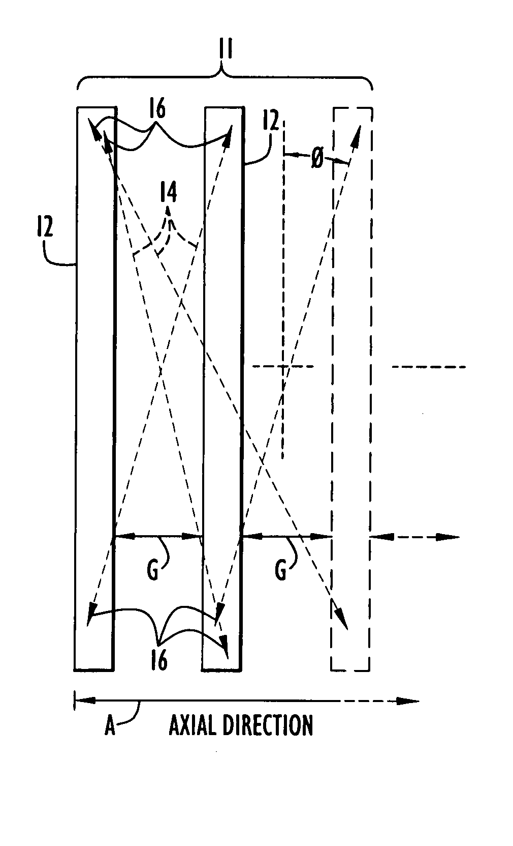
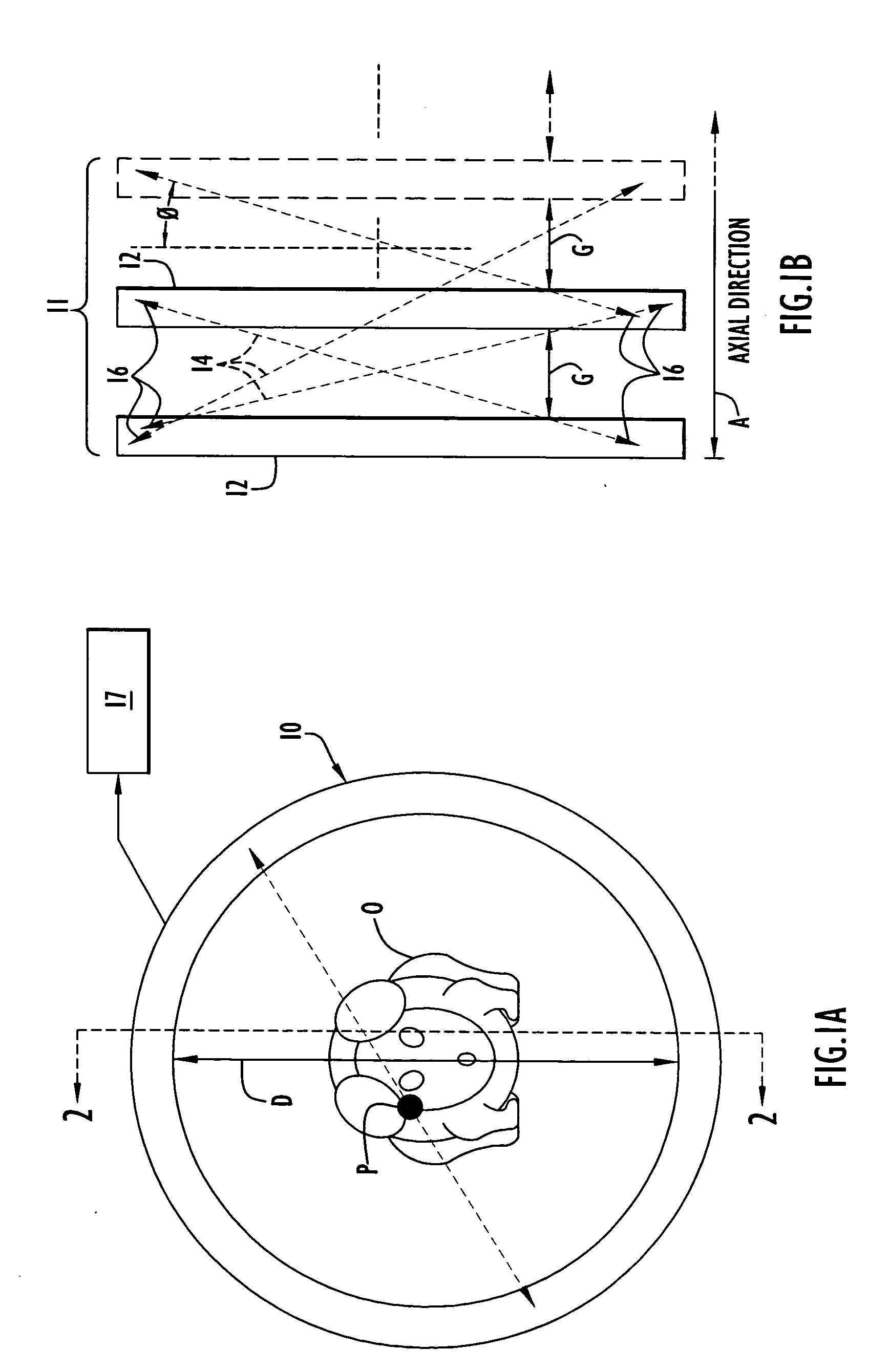
[0027] Tomography and tomographic images refer to images that together portray in three dimensions some property of an object being imaged. Commonly, such images may be in the form of a sequence of consecutive two dimensional transverse sections closely spaced along the axis of a tomography scanner to span the entire axial field-of-view of the scanner and the object therein. A “property” portray in such images can be, but it not limited to, the spatial distribution and frequency of occurrence of positron annihilation sites in the object, and a “property” may also refer to the distribution of attenuation coefficients, the location and amount of a light emitting compound distributed within the object, the amount and location of contrast material introduced into the object, and other such processes and phenomenon.

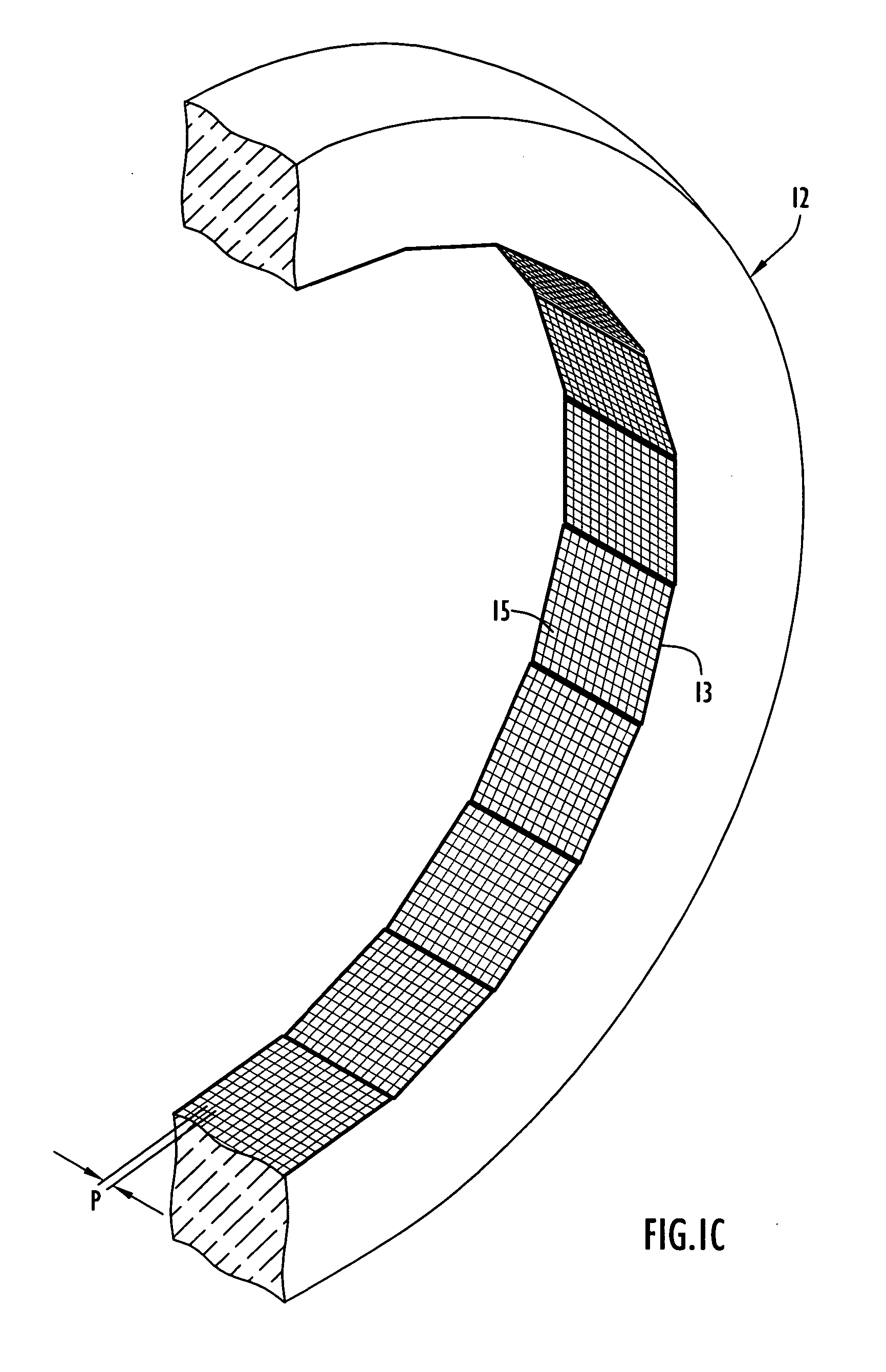
[0028] The term “detector ring” as used herein means an annular structure surrounding an imaging target or body formed of detector material that is responsive to incident rad...


PUM


Abstract

A tomography scanner has intentionally designed, well defined gaps between detector rings with image reconstruction obtained with the use of conventional tomography data processing. The scanner is particularly advantageous as a small animal PET scanner.

Description

CROSS REFERENCE TO RELATED PATENT APPLICATION [0001] This application claims priority from prior provisional patent application Ser. No. 60 / 504,321, filed Sep. 18, 2003, the entire disclosure of which is incorporated herein by reference.BACKGROUND OF THE INVENTION [0002] 1. Field of the Invention [0003] The present invention pertains to tomography scanners and, more particularly, to positron emission tomography (PET) scanners designed for imaging small animals or humans. [0004] 2. Brief Discussion of the Related Art [0005] Small animal PET scanners are commonly used in research facilities and, desirably, have high spatial resolution and uniformity and high sensitivity as described in “Molecular Imaging of Small Animals with Dedicated PET Tomographs,” Chatziioannou, Arion F., European Journal of Nuclear Medicine, Vol. 29, No. 1, January 2002. Commercial examples of such small animal PET scanners are the Concorde R4 and P4 “microPET” small animal PET scanners described in “Performance...

Claims


Application Information

Patent Timeline
IPC IPC(8): G01T1/166G21K
CPCG01T1/2985G01T1/1644G01T1/2008
Inventor VAQUERO, JUAN JOSESEIDEL, JURGENGREEN, MICHAEL V.
Owner TRIDENT IMAGING
Why Eureka
Try Eureka