
Yellow low fluorescence dye for coated optical bead random array DNA analysis

Inactive Publication Date: 2005-05-19
CARESTREAM HEALTH INC
View PDF9 Cites 5 Cited by
  • Summary
  • Abstract
  • Description
  • Claims
  • Application Information

AI Technical Summary

Benefits of technology

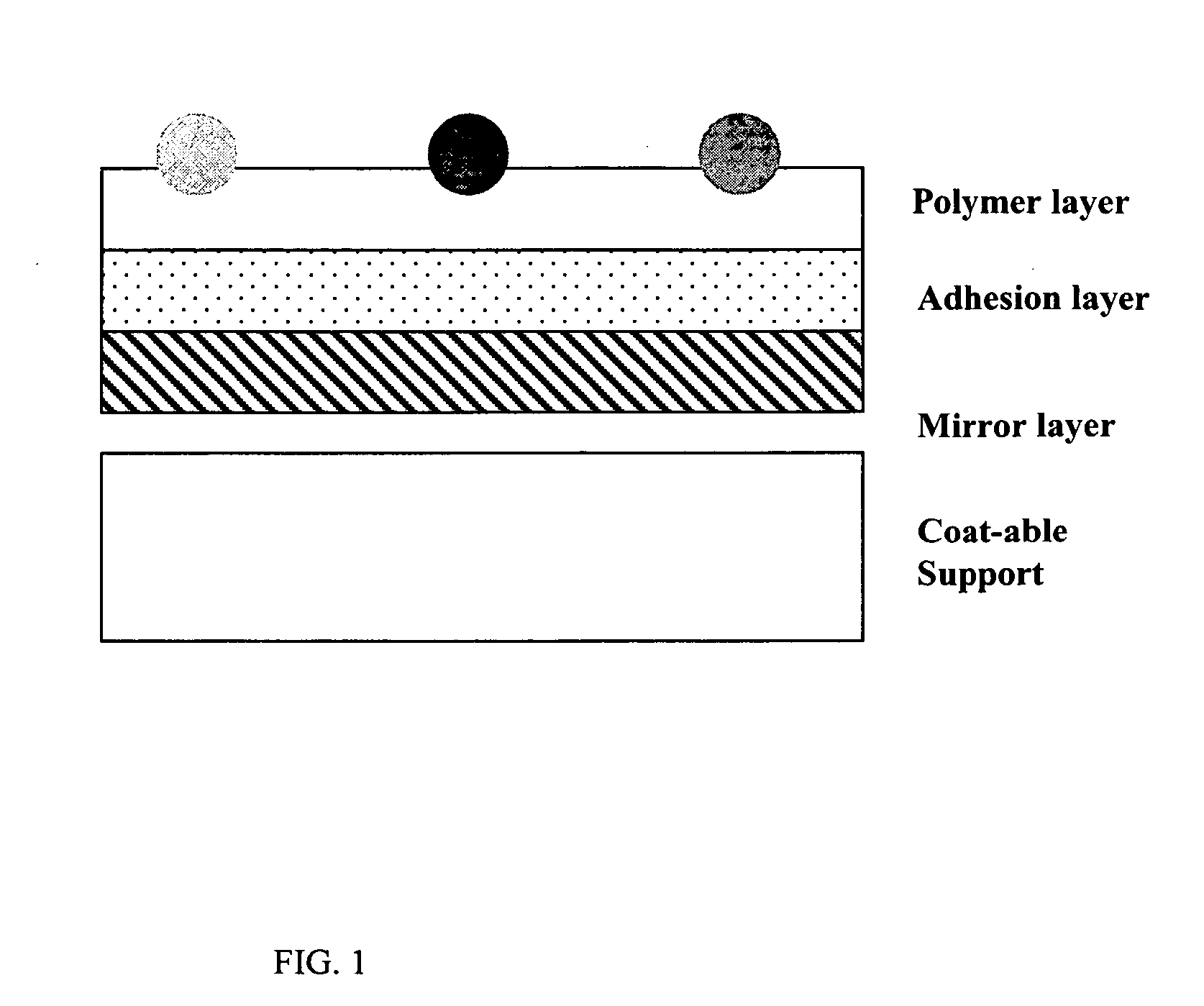
[0009] The invention utilizes a unique coating composition and technology to prepare a microarray on a substrate that may or may not be pre-etched with microwells and need not be premarked in any way with sites to attract the colored microspheres, as disclosed in the art. By providing the option of using unmarked substrates or substrates that need no pre-coating preparation, the present invention provides a huge manufacturing advantage compared to the existing technologies that do not provide the option. The invention discloses a method whereby color addressable mixed beads in a unique composition can be randomly distributed on a substrate that has no wells or sites to attract the microspheres.
[0010] The present invention provides a microarray that is less costly and easier to prepare than those previously disclosed, and further can be used in a colored microarray device such as described herein wherein red light absorbance is desired to be maximized and fluorescence of the dye imbibed in the colored polystyrene microsphere bead is desired to be minimized.

Problems solved by technology

This method is expensive.
An ink jet approach is being used by others (e.g., U.S. Pat. Nos. 6,079,283; 6,083,762; and 6,094,966) to fabricate spatially addressable arrays, but this technique also suffers from high manufacturing cost in addition to the relatively large spot size of 40 to 100 μm.
Because the number of bioactive probes to be placed on a single chip usually runs anywhere from 1,000 to 100,000 probes, the spatial addressing method is intrinsically expensive regardless how the chip is manufactured.

Method used


Image

  • Yellow low fluorescence dye for coated optical bead random array DNA analysis
  • Yellow low fluorescence dye for coated optical bead random array DNA analysis
  • Yellow low fluorescence dye for coated optical bead random array DNA analysis

Examples


example 1

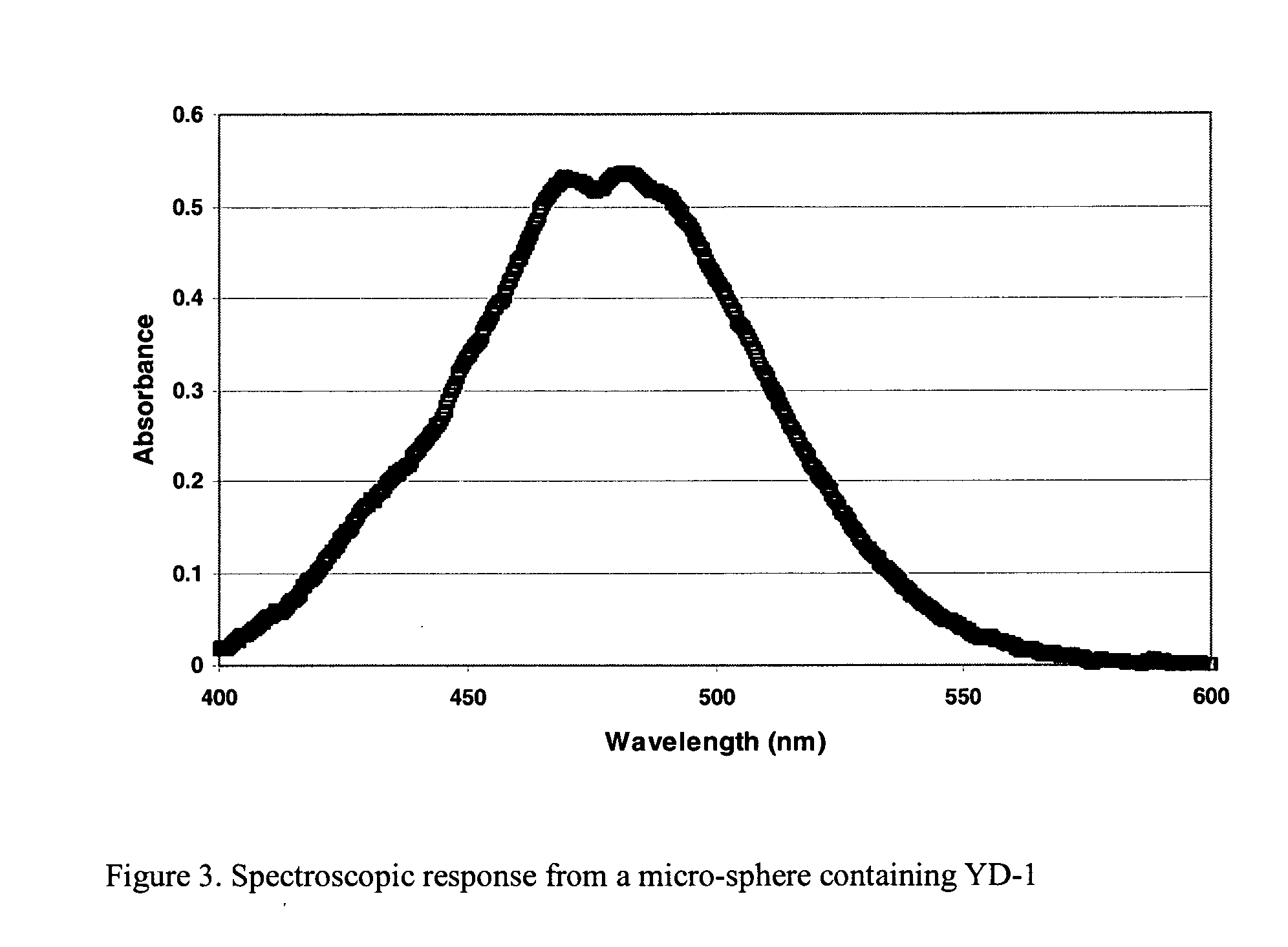
[0034] This example illustrates the colorant density obtained by using dye YD-1 (whose synthesis is described in JP 60032851) to color polystyrene microsphere beads.

[0035] A 4.2% aqueous suspension of polystyrene beads prepared by emulsion polymerization and having a mean size of 10 micrometers was obtained from Interfacial Dynamics Corporation, Portland, Oreg.

[0036] A suspension of yellow colored beads YD-1 was prepared by first dissolving 0.006 grams of YD-1 in 0.02 grams of toluene and 2 grams of acetone. 2.5 grams of the suspension of the above suspension of non-dyed (clear) beads was combined with 3 grams of acetone. This mixture was then added rapidly to the solution of YD-1 in acetone and toluene while stirring to prepare a suspension of colored beads. The suspension of colored beads was then filtered using a porous cotton filter, poured into a dialysis bag (12,000 to 14,000 molecular weight cut off) and washed with distilled water for one hour. fter washing, the suspension...

example 2

[0054] This example illustrates the very low fluorescence obtained in polystyrene microsphere beads colored with YD-1.

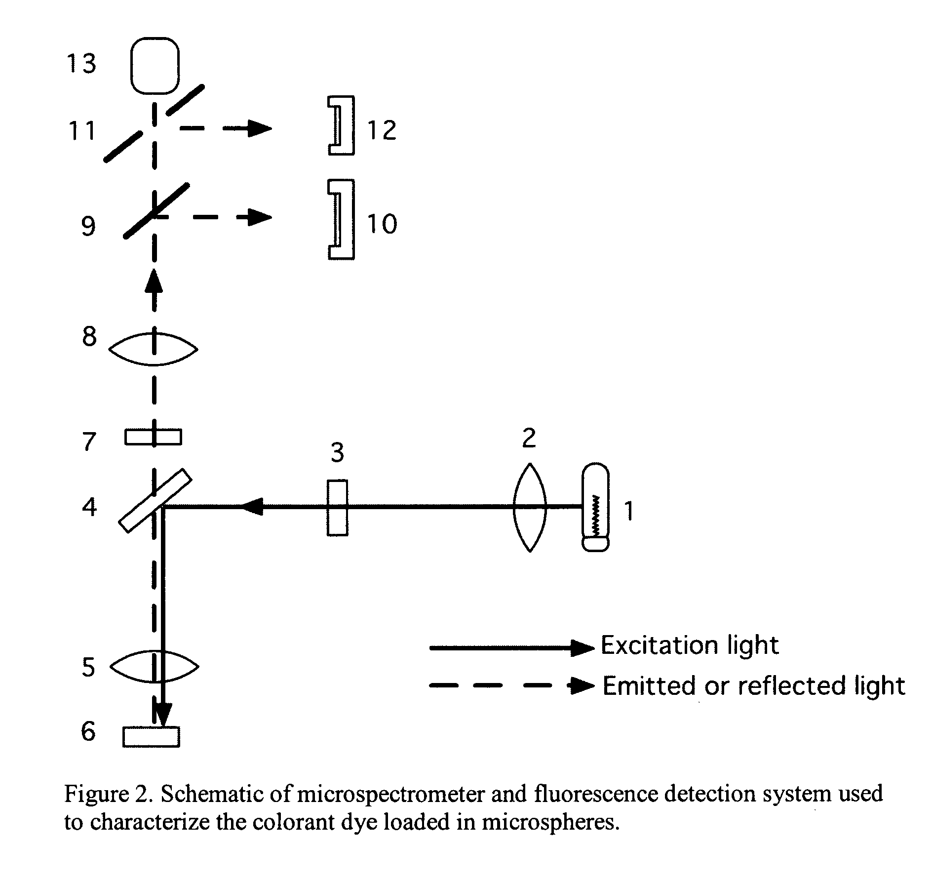
[0055] Comparison of the fluorescence intensity variation in several yellow dyes was made using the hybrid analytical system described above. By incorporating fluorescence cubes, each consisting of an exciter filter, 3 in FIG. 2, a dichroic mirror, 4, and a barrier filter, 7, the fluorescence emission characteristics of a colorant can be monitored. The spectroscopy data was used to select the wavelength characteristics of the fluorescence cube. For the yellow dyes used in this invention application, the excitation filter was selected to band pass light in the 550-580 nm region, the dichroic mirror was capable of passing light >600 nm in wavelength, and the barrier filter had a high pass characteristic of >610 nm. By setting the spectrometer to collect fluorescence emission intensity for a fixed time (1 second), while keeping other experimental conditions constant, c...


PUM

PropertyMeasurementUnit
Diameteraaaaaaaaaa
Diameteraaaaaaaaaa
Diameteraaaaaaaaaa

Abstract

A coating composition for making a protein microarray, the composition comprising a gelling agent or a precursor to a gelling agent and microspheres; the microspheres containing a dye represented by Formula (I): wherein: R1 and R2 independently reprresent substituted or unsubstituted alkyl, aryl, carbocyclic ring, heterocyclic ring, or amino; and R3 represents H, alkylamino, dialkylamino, hydroxy, or alkoxy.

Description

CROSS-REFERENCE TO RELATED APPLICATIONS [0001] Reference is made to commonly-assigned, copending U.S. patent application Ser. No. ______ (DN85501), entitled MAGENTA LOW FLUORESCENCE DYE FOR COATED OPTICAL BEAD RANDOM ARRAY DNA ANALYSIS and copending U.S. patent application Ser. No. ______ (DN85500), entitled CYAN LOW FLUORESCENCE DYE FOR COATED OPTICAL BEAD RANDOM ARRAY DNA ANALYSIS, both filed of even date herewith. Reference is also made to U.S. Publication No. 2000-68609, filed Aug. 29, 2001, entitled RANDOM ARRAY OF MICROSPHERES. The copending applications are incorporated by reference herein for all that they contain.FIELD OF THE INVENTION [0002] The present invention concerns biological microarray technology in general. In particular, the invention concerns the coloration of polystyrene microspheres or “beads” coated on a substrate to form a microarray. BACKGROUND OF THE INVENTION [0003] Ever since it was invented in the early 1990s (Science, 251, 767-773, 1991), high-density ...

Claims


Application Information

Patent Timeline
IPC IPC(8): B01L99/00C07C251/08C07D295/185C12M1/34
CPCC07D295/185C07C251/08
Inventor CHARI, KRISHNANQIAO, TIECHENG A.DIEHL, DONALD R.CHEN, SAMUEL
Owner CARESTREAM HEALTH INC
Learn More