Needle aspiration biopsy device and method

Inactive Publication Date: 2005-05-12
MCW RES FOUND INC
View PDF47 Cites 127 Cited by
  • Summary
  • Abstract
  • Description
  • Claims
  • Application Information

AI Technical Summary

Benefits of technology

[0016] The present invention provides a needle aspiration biopsy, or FNAB, device, with an anti-reflux head designed specifically to increase the yield of specimens obtained during the biopsy procedure. The anti-reflux head transfers the specimens from the needle to the top of a collection well in a wide-mouth hub. Preferably, the vacuum in the needle is initiated and terminated while the needle is inserted into the tissue. Moreover, the needle can have special side scoops for increasing the amount of specimens collected on each pass of the needle through the specimen sample site, such as a tumor, lesion or other soft tissue region of interest.
[0017] In particular, one aspect of the present invention provides a high specimen yield anti-reflux head for a needle aspiration biopsy device including a unique hub. The hub defines a collection wall and mounts a needle with an open pointed tip. A passageway is defined by one or both of the needle and hub which extends from the pointed tip of the needle to a segment extending inside the hub opening in spaced relation to a floor of the collection well.
[0023] Another aspect of the invention provides an anti-reflux FNAB device. The FNAB device includes a syringe with a barrel and a sliding piston, a valve for controlling flow to and from the syringe and the anti-reflux head described above. One or more piston locks can be snapped onto the shaft of the piston to hold in place and maintain the vacuum. The FNAB device can also include a sheath stand as described above to conceal the needle as well as to support the device upright. The valve gives the physician or technician precise, one-handed control of the vacuum at the needle so that it can be both initiated and terminated while the needle is within the specimen sample site. This establishes a vacuum suitable to withdraw specimens into the collection well while preventing reflux back into the needle.

Problems solved by technology

Conventional FNAB techniques can often yield insufficient specimens to conduct a thorough diagnostic analysis.
This problem arises because of several deficiencies in conventional FNAB devices, particularly with regard to the delivery of the specimens into the needle, their retention in the device, and their transfer from the device to the diagnostic stage or vessel.
Among other things, these deficiencies are in part due to the insufficient space for specimens, the way the specimens are introduced into the device and the way the vacuum is achieved and released.
In conventional FNAB devices specimens are susceptible to being drawn into the syringe barrel under vacuum or lost be reflux back through the needle, in both cases diminishing the overall yield usable for analysis.
This problem is exacerbated by coagulation of the aspirated specimens in the collection chamber.
Another problem with the small collection space is that small micro-specimen or portions of the accumulated specimens cannot be readily transferred to the examination site in a controlled manner.
The narrowness of the opening essentially requires the specimens to be dumped or poured out into the test tube or onto the slide, and thus the more accurate “pick and spread” transfer method may not be used because conventional forceps may be too large.
This device is disadvantageous, however, because collected specimens are lost by reflux back through the needle.
As illustrated by the above patent, conventional FNAB devices are susceptible to losing part of the sample through reflux of the collected specimens back through the needle.
The typical way to make up for the specimens lost by reflux is to conduct multiple biopsies and / or increase the number of probes into the tissue per biopsy, thus increasing the time of the procedure and the patient's discomfort.
Two problems with these devices are that there is no provision for adequately retaining sufficient quantities of specimens or for transferring the specimens in a controlled manner.
However, reflux is likely when a relatively large amount of specimens is collected, as when a significant portion of the hollow piston was filled.
Consequently, the reflux problem would remain.
Another issue with this device is that it is designed for use with a centrifuge, and thus, given the length of the piston, is not well suited for the pick and spread transfer method.

Method used


Image

  • Needle aspiration biopsy device and method
  • Needle aspiration biopsy device and method
  • Needle aspiration biopsy device and method

Examples


Embodiment Construction

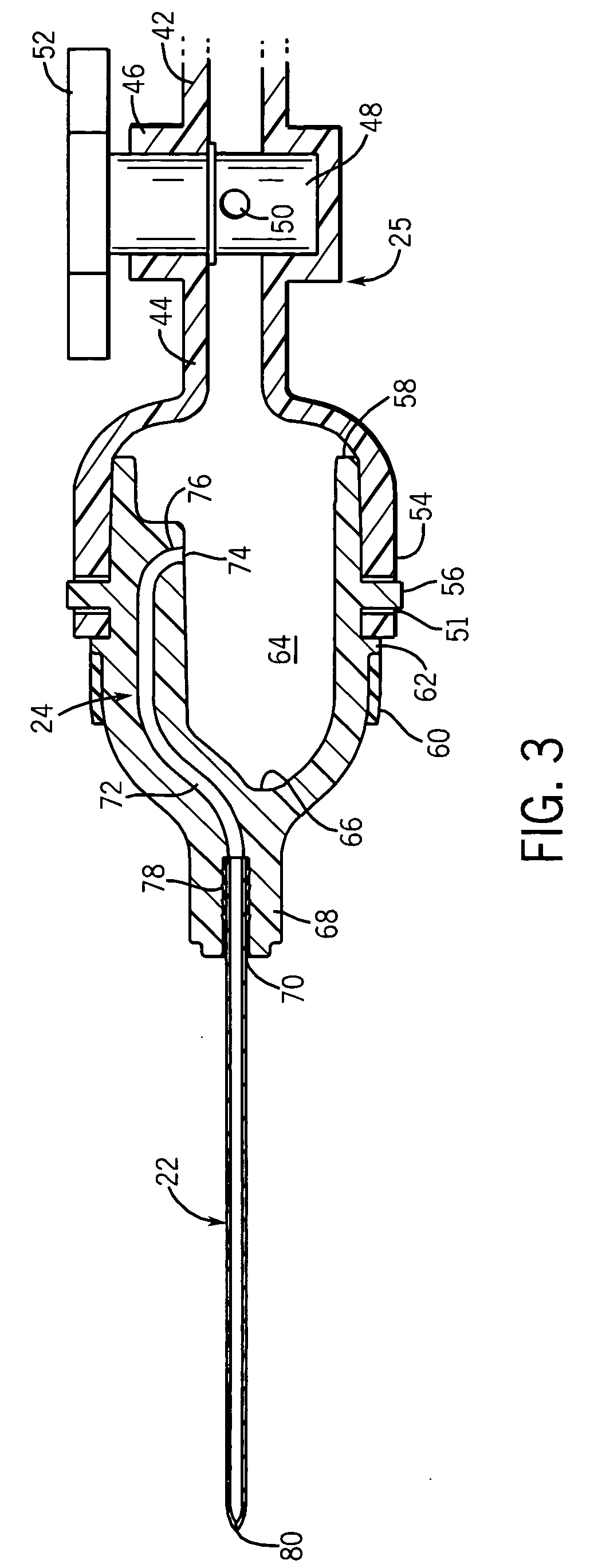
[0043] The present invention provides an FNAB device with an anti-reflux head designed specifically to increase the yield of tissue specimens obtained during the biopsy procedure. The anti-reflux head transfers the specimens from the needle and deposits them down into a collection well in a wide-mouth hub. Preferably, the vacuum in the needle is initiated and terminated while the needle is inserted into the specimen sample site, which could be a tumor, lesion or other soft tissue region of interest. Moreover, the needle can have special side scoops for increasing the specimen yield from each pass of the needle through the site.

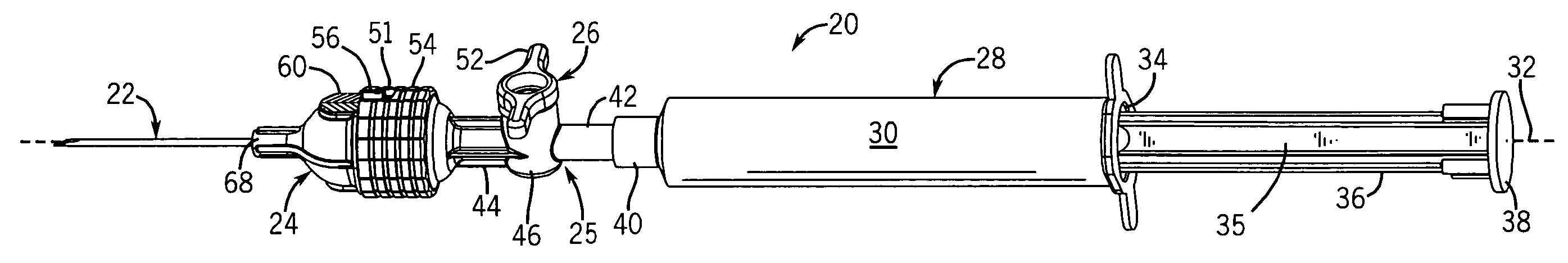
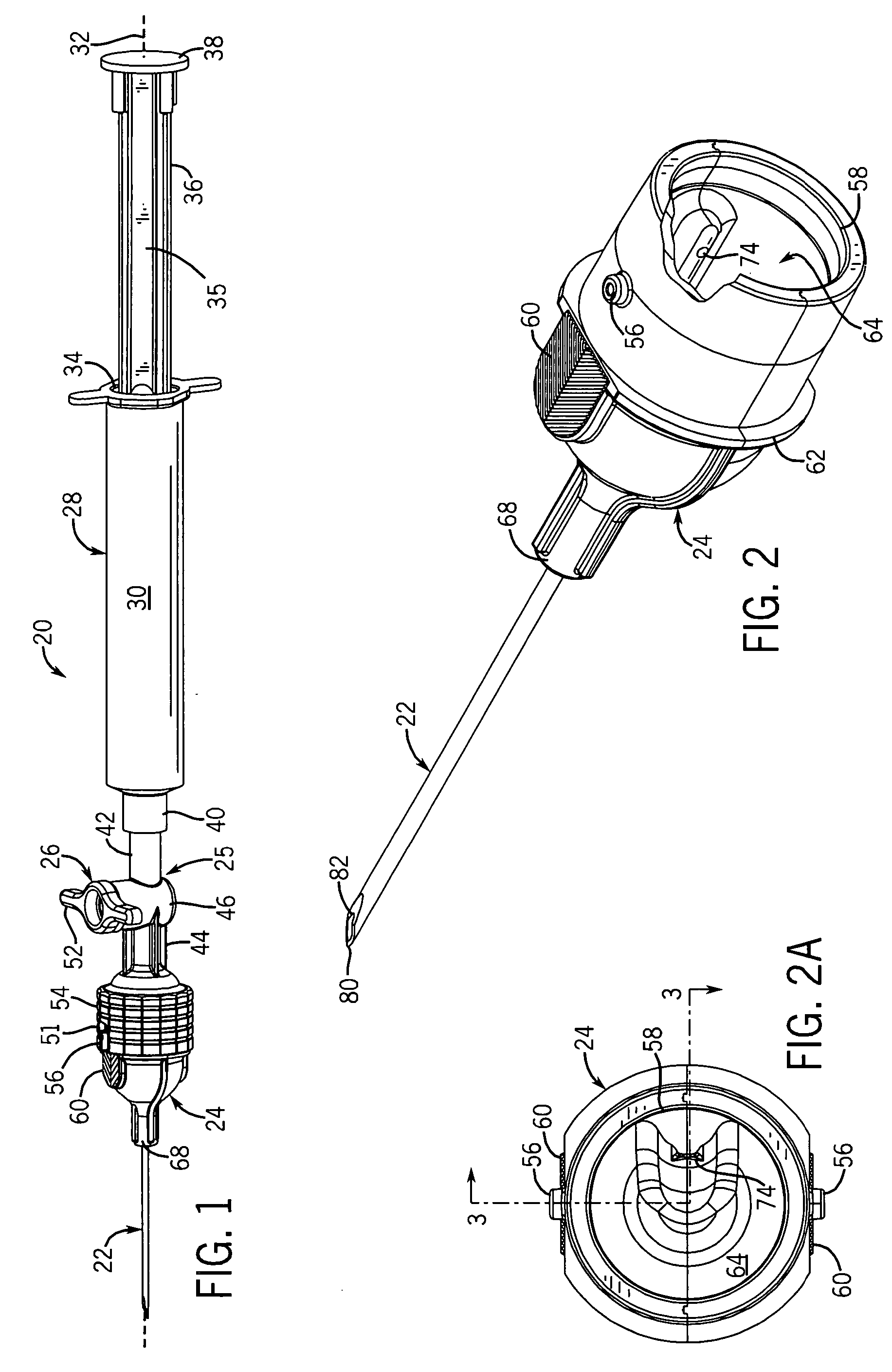
[0044] Referring now to FIGS. 1 and 4, the FNAB device 20 generally includes a needle 22 mounted to a hub 24 which is connected by a coupler 25, having a valve 26, to an end of a syringe 28. The syringe 28 is generally of standard construction having a tubular barrel 30, extending along a longitudinal axis 32, with a narrow opening (not shown) at one end and ...


PUM


Abstract

A needle aspiration biopsy device includes a syringe, a valve coupler for controlling a vacuum in the syringe barrel, and an anti-reflux head. The head includes a hub, defining a large collection well preferably several hundred micro liters in volume, and a needle mounted to the hub. A passageway is defined either by a contoured needle or a straight needle and an internal channel in the hub wall such that a proximal end of the passageway extends inside the hub and opens in spaced relation to a floor of the collection well. A method of biopsy using the device is also disclosed.

Description

CROSS-REFERENCE TO RELATED APPLICATIONS [0001] This application claims benefit to U.S. provisional patent application Ser. No. 60 / 518,069 filed on Nov. 6, 2003.STATEMENT OF FEDERALLY SPONSORED RESEARCH OR DEVELOPMENT [0002] Not applicable. BACKGROUND OF THE INVENTION [0003] 1. Field of the Invention [0004] The present invention relates to medical devices, and in particular to needle aspiration biopsy devices. [0005] 2. Background of the Art [0006] Fine needle aspiration biopsy (hereinafter “FNAB”) is a widely practiced technique for acquiring diagnostic sample specimen of various tumors and lesions, and is generally considered a safe, rapid and economical non-surgical alternative to conventional surgical biopsy. [0007] The FNAB technique is conventionally practiced with a standard hypodermic needle syringe with a fine gauge needle, possibly suited with special syringe grips and modified to include a small specimen collection chamber at the base of the needle. The FNAB technique as c...

Claims


Application Information

Patent Timeline
IPC IPC(8): A61B10/00A61B10/02
CPCA61B10/0283A61B10/0275
Inventor SHIDHAM, VINOD B.SHIDHAM, ANJANI
Owner MCW RES FOUND INC
Why Eureka
Try Eureka