
Method of making open cell material

a technology of open cell material and ceramics, which is applied in the field of porous materials, can solve the problems of unsuitable foaming of powder, and achieve the effect of convenient flow

Inactive Publication Date: 2005-05-12
NAT RES COUNCIL OF CANADA +1
View PDF35 Cites 46 Cited by
  • Summary
  • Abstract
  • Description
  • Claims
  • Application Information

AI Technical Summary

Benefits of technology

[0029] It has been found surprisingly that open cell materials with unique microstructure can be obtained by using a dry powder mixture. Such as mixture can be made easily flowable. Generally, it would be thought that a powder would not be suitable for foaming because the released gases would tend to flow around the particles and escape without creating a foam.
[0034] Optionally, a cross-linking agent may be added to the dry powder mixture to cure the binder and improve the mechanical strength of the foamed structure before debinding.
[0035] Optionally, 0.05 wt % to 5 wt %, but preferably between 0.1 to 0.5 wt % additional binder may be added to minimize segregation and dusting and improve the flowability of the dry powder mixture.
[0036] Optionally, spacing agents may be used to provide additional porosity and to improve pore connectivity. The spacing agent can be particles that are added to the initial powder formulation or a scaffold. The scaffold can be for example a polymeric foam. The spacing agents are removed after foaming to leave voids in the structure after debinding or sintering. The spacing agent can be removed by thermal decomposition after foaming or by leaching after foaming, debinding or sintering.

Problems solved by technology

Generally, it would be thought that a powder would not be suitable for foaming because the released gases would tend to flow around the particles and escape without creating a foam.

Method used


Image

  • Method of making open cell material
  • Method of making open cell material
  • Method of making open cell material

Examples


example 1

[0064] Ni foams were produced with the formulation presented in Table 1. The different constituents were dry-mixed together. After mixing, the powder was poured into a mold and foamed at 150° C. in air. After foaming, the material was submitted to the debinding step in a tube furnace at 500° C. for 4 h in a dry air stream. Finally, the specimens were sintered in Ar-10% H2 for 2 h at 750° C.

TABLE 1Formulation used for the fabrication of the Ni foams.MetallicFoaming agentPowderBinderP-toluene sulfonylNi powderPhenolic resinhydrazide70.18 wt. %29.32 wt. %0.5 wt. %

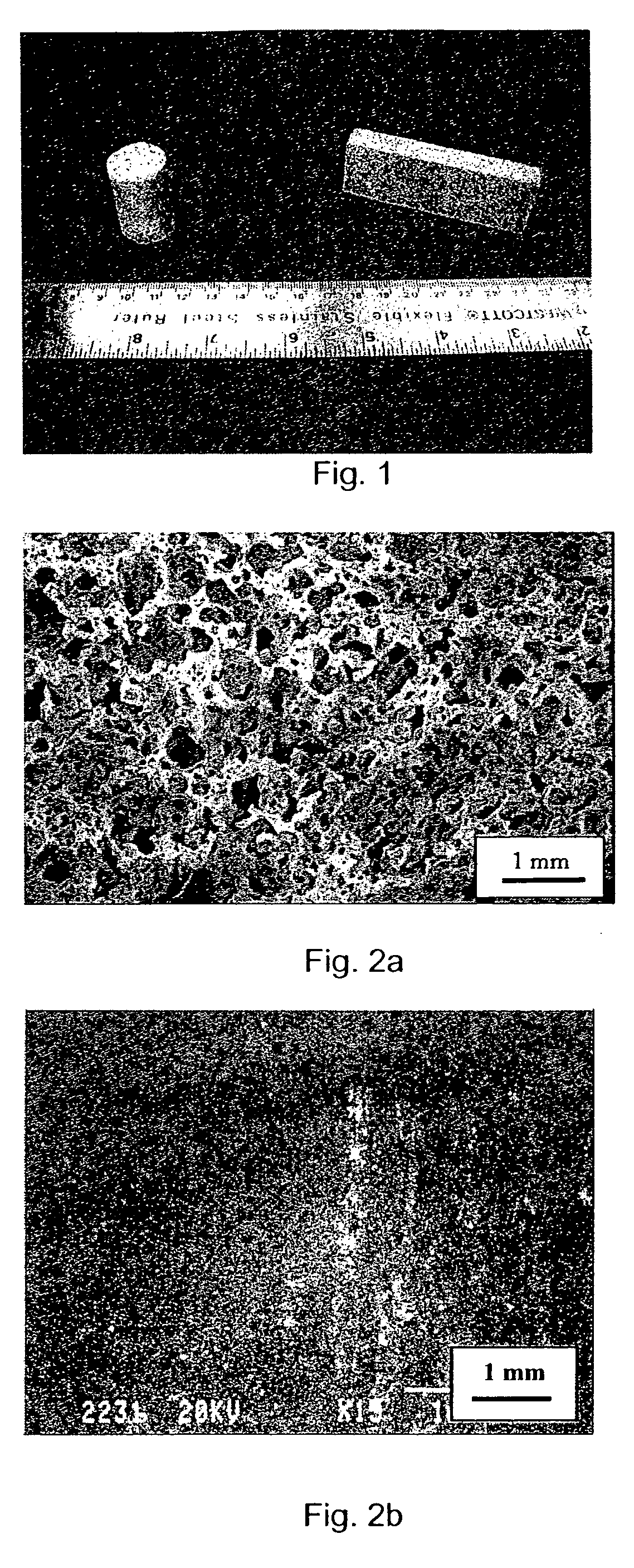
[0065]FIG. 1 shows machined specimens obtained with the formulation of Table 1. The specimens were machined from plates and tubes after sintering. Table 2 shows that the density of the foamed material is significantly smaller than that of a material obtained by loose sintering without using binder and foaming agent. The density of the foam is almost 10 times smaller than that of pure solid nickel.

TABLE 2Density of a Ni foa...

example 2

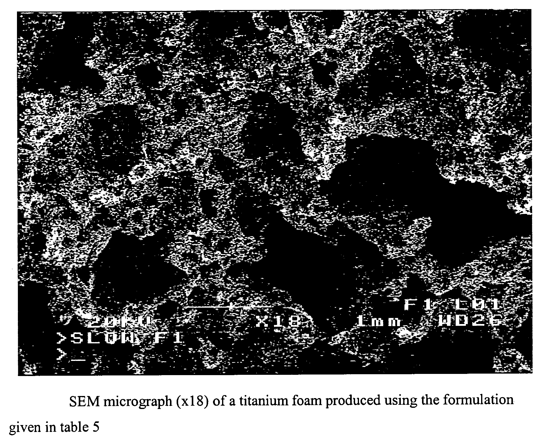
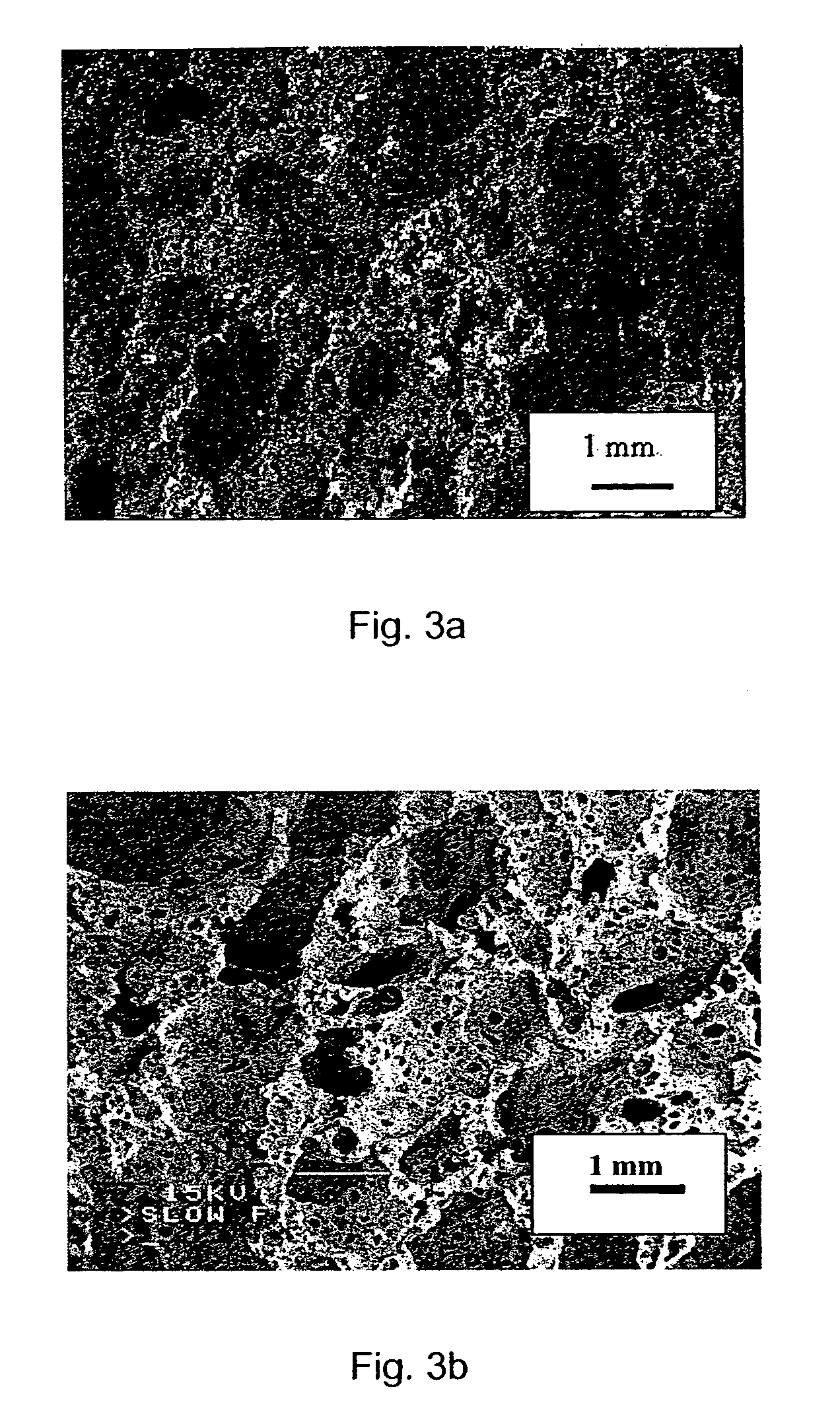
[0067] Foams were produced with the formulations presented in Table 3, using the procedure described in Example 1. Depending on the formulation, it is possible to produce different materials. The microstructure of copper and iron foams is presented in FIGS. 3a and 3b. It is also possible to modify the microstructure of the material by modifying the mixture composition. Another way to modify the structure and properties of the material is to modify the foaming process parameters. In fact, the microstructure of a material foamed at 190° C. with the formulation given in Table 1 is presented in FIG. 4. The pore size of the material foamed at 190° C. is significantly larger than that of the material foamed at 150° C. (FIG. 2a).

TABLE 3Formulations used for the fabrication of different metallic foams ofExample 2.MetallicFoaming agentPowderBinderP-toluene sulfonylPowderPhenolic resinhydrazide  75 wt. % Ni24.25 wt. %0.75 wt. %70.18 wt. % Cu29.32 wt. % 0.5 wt. %70.18 wt. % Fe29.32 wt. % 0.5...

example 3

[0068] Ni foams were produced with the formulation presented in Table 3 using a thermoplastic binder. The different constituents were dry-mixed together. After mixing, the powder mixture was poured into a mold, compressed to a density of 2.28 g / cm3 and heated at 180° C. in air to melt the binder and induce the foaming. The foamed material was further submitted to the debinding step in a tube furnace at 500° C. for 4 h in a dry air stream. Finally, the specimens were sintered in Ar-10% H2 for 2 h at 750° C.

TABLE 4Formulation used for the fabrication of the Ni foams.MetallicBinderFoaming agentPowderPolyethylenep,p′-oxybis (benzeneNi powderpowdersulfonyl hydrazide)79.5 wt. %18 wt. %2.5 wt. %

[0069]FIG. 4 presents a section of a specimen obtained with the formulation of Table 4. The material has maintained its porous structure after sintering. It is highly porous and has three level of porosity. The porosity is interconnected. This porous material has a sintered density of 1.55 g / cm3. ...


PUM

PropertyMeasurementUnit
Temperatureaaaaaaaaaa

Abstract

The porous material of the present invention is produced by heating a dry powder mixture, containing mainly an organic solid binder and inorganic particles. The mixture is foamed while the organic binder is melted. Foaming comes from a foaming agent in the powder mixture. The solid foamed structure comprising inorganic particles embedded in an organic binder is then heated to eliminate the organic binder and finally to sinter the remaining inorganic tri-dimensional network into a rigid structure having interconnected porosity.

Description

CROSS REFERENCE TO RELATED APPLICATION [0001] This application is a continuation-in-part of co-pending application Ser. No. 09 / 938,638 filed Aug. 27, 2001.BACKGROUND OF THE INVENTION [0002] 1. Field of the Invention [0003] This invention relates to the field of porous materials, and in particular to a method of making an open cell metal or ceramic material. [0004] 2. Description of Related Art [0005] Porous metal or ceramic materials are currently used for the fabrication of devices such as filters, heat exchangers, sound absorbers, electrochemical cathodes, fuel cells, catalyst supports, fluid treatment units, lightweight structures and biomaterials. The structures (open / closed porosity, pore size distribution and shape, density) and properties (permeability, thermal, electrochemical and mechanical properties) required greatly depend on the application. Closed porosity is generally sought for lightweight structure while open porosity is particularly seek when surface exchange are i...

Claims


Application Information

Patent Timeline
IPC IPC(8): B22F3/11C04B38/06
CPCB22F3/1125B22F2003/1131C04B38/061C04B35/00C04B38/0074C04B38/02C04B38/062C04B38/0635C04B40/0042C04B38/10
Inventor LEFEBVRE, LOUIS-PHILIPPETHOMAS, YANNIGGAUTHIER, MAXIME
Owner NAT RES COUNCIL OF CANADA
Learn More