Transmission systems

a transmission system and transmission shaft technology, applied in the field of transmissions, can solve the problems of unworkable lateral movement of inner and outer shafts, and inability to work, and achieve the effect of minimizing slippage and high surface conta

Inactive Publication Date: 2005-05-12
VAN COR DALE E
View PDF8 Cites 10 Cited by
  • Summary
  • Abstract
  • Description
  • Claims
  • Application Information

AI Technical Summary

Benefits of technology

[0030] It is a further aspect of the invention to provide a transmission system in which the portion of teeth engaged in the conic teeth engages the cone frictionally as well, creating a high surface contact and minimizing slippage.

Problems solved by technology

Fourth, the embodiment of the VCT described in FIG. 62 of the '407 application will not work with the VCT2, as the shaft of the pinion gear is for controlling the position of the gear.
Fifth, the VCT Felch cascade configuration will not work with the VCT2 because the cone cannot move independently and lateral movement of the inner and outer shaft would be unworkable.
Sixth, the Persson configuration of the VCT2, will not work with the VCT because the axes of all gears are parallel to each other.
Although both the VCT and VCT2 are well suited to a wide variety of applications, they are not well suited for hostile environments and are not cost effective for some low cost applications.
Accordingly, the VCT and VCT2 are physically limited in how fast they can change speeds due to this position tracking.
In addition, the VCT and VCT2 are neither cheap nor simple to make and, therefore, are not well suited for lawn tractor and other low torque, low cost applications.

Method used


Image

  • Transmission systems
  • Transmission systems
  • Transmission systems

Examples


Embodiment Construction

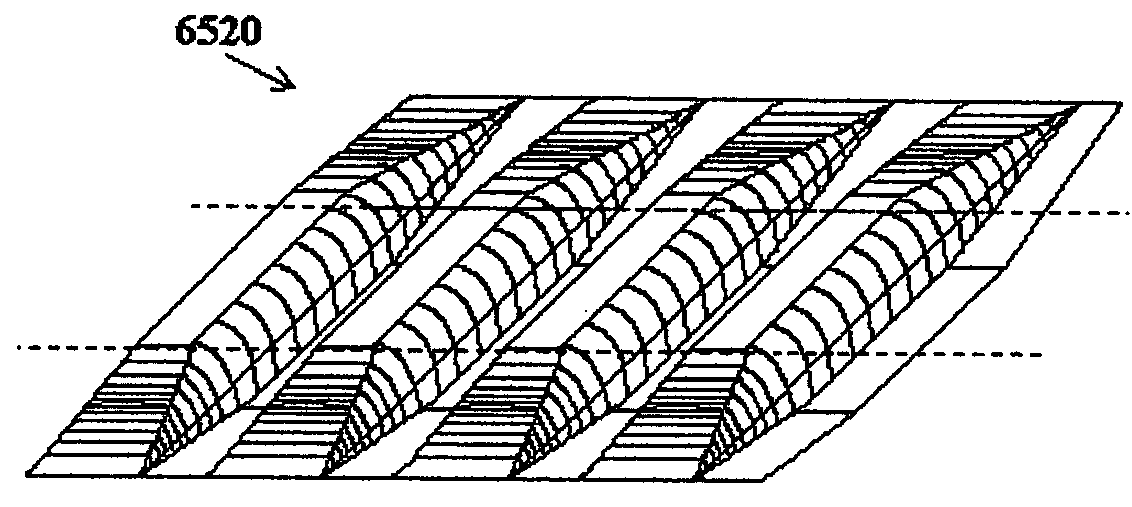
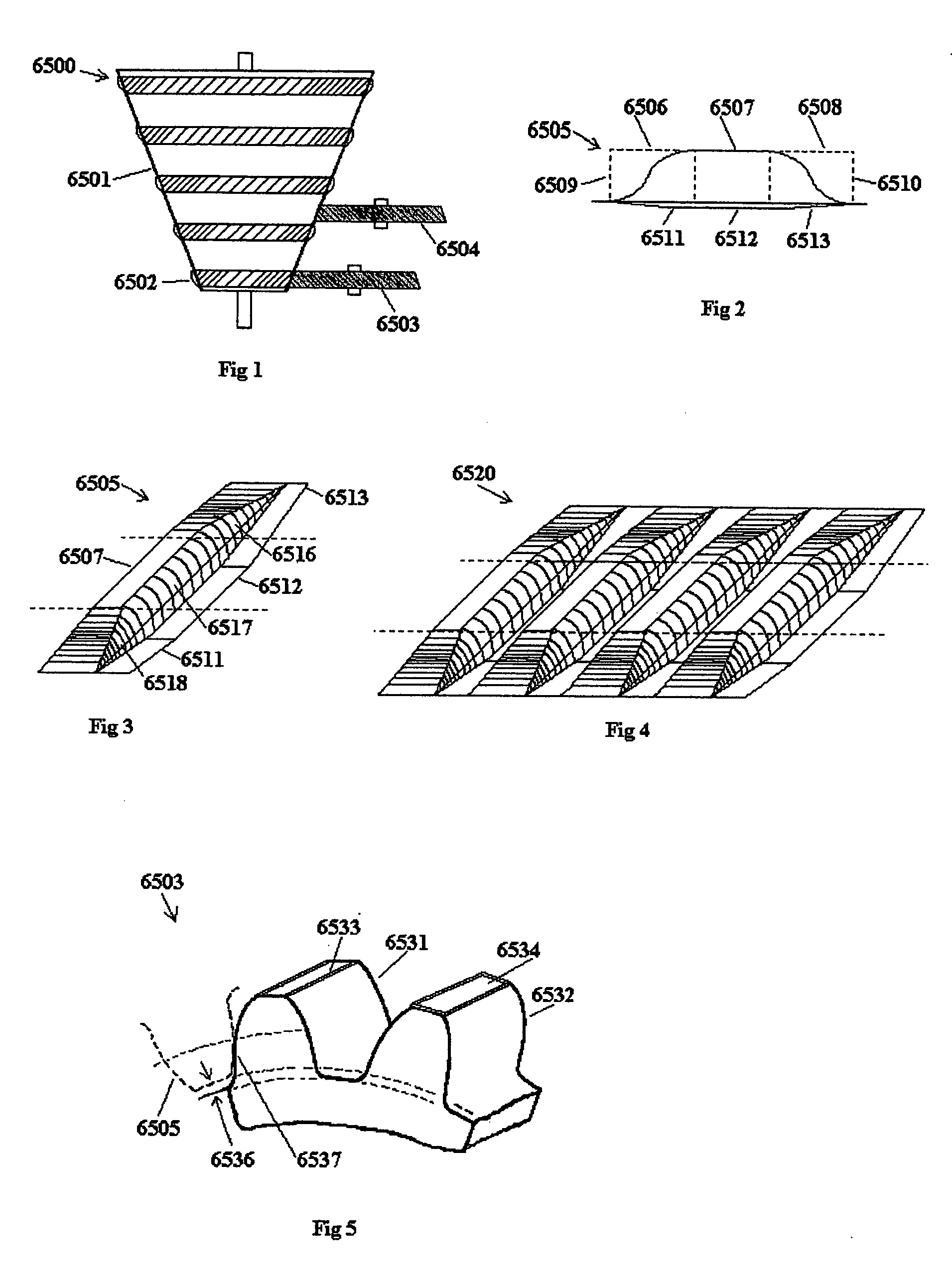
[0079] The basic principle of a friction tooth drive 6500 is explained with reference to FIGS. 1-5. Cone 6501 with ring teeth 6502 is engaged with a conic gear 6503. This is an Ashbey surface interface. A side view of a ring tooth 6502 on the friction tooth cone, referred to herein as a “friction tooth 6505” is shown in FIG. 2 as a conic tooth with portions 6509, 6510 removed; leaving sloped ends 6506, 6508 and a mid-section 6507. The mid-section 6507 is where normal tooth engagement occurs. The sloped ends have two functions; it provides the friction tooth 6505 with a place to slide onto a conic tooth converting from a friction to a tooth drive, and provides the friction tooth 6505 with a place to slide from a conic tooth to a friction surface converting back to a friction drive. The tooth space 6511, 6512, 6513 in FIG. 2 and FIG. 3 shows the cone's surface ramping down 6511 to a normal clearance space 6512 for meshing teeth. When the friction tooth 6505 is slid from the conic teet...


PUM


Abstract

A transmission that functions as a combination friction drive and gear tooth drive: The transmission utilizes VCT conic teeth added to the surface of a variable pulley. The teeth in the sides of a continuous loop, or a two-faced gear, engage the teeth on this conic surface. When the pulleys contract or expand, the top of the teeth engage the surface frictionally. When the contraction or expansion of the pulleys move the continuous loop, or two-faced gear, to the next ring of conic teeth, it engages the conic teeth as a toothed drive.

Description

CLAIM OF PRIORITY [0001] This application claims the benefit of priority of U.S. Provisional Patent Application Ser. No. 60 / 502,708, filed Sep. 12, 2003.FIELD OF THE INVENTION [0002] The present invention relates to the field of transmissions and, in particular, to transmissions utilizing cones to vary the speed of transmission components. BACKGROUND OF THE INVENTION [0003] The inventor of the present application is the inventor of two related and co-pending applications, which each disclose arrangements of gears and systems utilizing these arrangements. U.S. Pat. No. 6,543,305, invented by the inventor of the present invention and incorporated herein by reference, discloses and claims a gear train and transmission system called the VCT and is hereafter referred to as the “VCT patent”. U.S. Pat. No. 6,499,373, also invented by the inventor of the present invention and incorporated herein by reference, discloses and claims a stack of gears and transmission system called the VCT2 and ...

Claims


Application Information

Patent Timeline
Patent Type & Authority Applications(United States)
IPC IPC(8): F16H3/36F16H9/08F16H9/20F16H15/20F16H15/22F16H48/06
CPCF16H3/363F16H9/08Y10T74/19972F16H15/20F16H15/22F16H9/20
Inventor VAN COR, DALE E.
Owner VAN COR DALE E
Why Eureka
Try Eureka