
Charged particle beam apparatus and automatic astigmatism adjustment method

a technology of chargeable particle beam and astigmatism adjustment, which is applied in the direction of optical radiation measurement, instruments, heat measurement, etc., can solve the problems of deteriorating length measurement performance, inspection sensitivity, and degradation of electron beam image quality, and achieve high degree of accuracy and minimize damage to subject samples

Inactive Publication Date: 2005-05-05
HITACHI LTD
View PDF17 Cites 7 Cited by
  • Summary
  • Abstract
  • Description
  • Claims
  • Application Information

AI Technical Summary

Benefits of technology

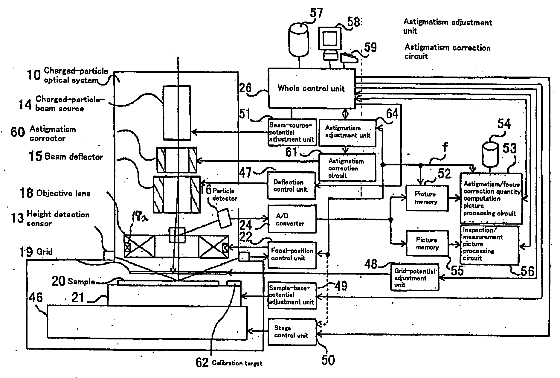
[0008] According to the invention, techniques for automatically adjusting for astigmatism in a charged particle beam apparatus are provided. Embodiments according to the present invention can provide a charged particle beam apparatus and an automatic astigmatism adjustment methods capable of automatically correcting astigmatism and a focal point in a relatively short period of time by finding a plurality of astigmatism correction quantities and a focal point correction quantity in a single operation from a relatively small number of 2 dimensional images. Specific embodiments can perform such automatic focusing while minimizing damages inflicted on subject samples. Embodiments include, among others, a charged particle optical system for carrying out an inspection, a measurement and a fabrication with a relatively high degree of accuracy by using a charged particle beam.
[0009] Numerous benefits are achieved by way of the present invention over conventional techniques. The present invention can provide specific embodiments with the capability of automatically adjusting astigmatism and a focal point at a relatively high speed and with a relatively high degree of precision by using a small number of particle images obtained as a result of radiation of a converged charged particle beam to a sample in a scanning operation without inflicting a damage on the sample. In addition, select embodiments according to the present invention can also provide the capability of carrying out an automatic inspection of a pattern defect, such as a foreign substance on an object substrate, or an automatic measurement of dimensions of a pattern on the object substance. In specific embodiments, such tasks can be carried out with a relatively high degree of precision while sustaining the quality of a particle image in a relatively stable manner over a relatively long period of time by using the particle image. The particle image is obtained as a result of radiation of a converged charged particle beam while adjusting astigmatism and focal point thereof automatically and at a relatively high speed and with a relatively high degree of precision.
[0010] Select embodiments according to the present invention can provide a charged particle beam apparatus and an automatic astigmatism adjustment method capable of automatically correcting astigmatism in a relatively short period of time for a variety of samples. Such embodiments according to the invention can find a plurality of astigmatism correction quantities at the same time from a small number of 2 dimensional images. In specific embodiments, damage inflicted on samples can be kept to a minimum.
[0011] Furthermore, some specific embodiments according to the present invention can provide a charged particle beam apparatus capable of carrying out inspections, measurements and fabrications with a relatively high degree of reliability and in a relatively stable manner over a relatively long period of time. The quality of a charge particle image obtained from an object substrate as a result of automatic correction of astigmatism and a focal point of a charged particle beam optical system is improved in some embodiments.
[0012] Moreover, many specific embodiments according to the present invention can provide a sample used for an adjustment of astigmatism and a focal point of a charged particle beam and suitable for an automatic correction of the astigmatism and the focal point in a relatively short period of time by suppressing damages inflicted on the sample to a minimum in a charged particle beam optical system.
[0013] Yet further, some specific embodiments according to the present invention can provide an automatic astigmatism adjustment method capable of automatically correcting astigmatism and a focal point in a relatively short period of time from a 2 dimensional particle image and to provide a sample for the method.

Problems solved by technology

The quality of an electron beam image deteriorates due to causes such as astigmatism of the electron beam system and degradation of the resolution attributed to defocusing.
A poor quality electron beam image causes the inspection sensitivity and the performance of the length measurement to deteriorate.
In addition, in such an image, the pattern width varies and a result of detection of an image edge can not be obtained in a relatively stable manner.
In consequence, results of measuring the wire width of a pattern and the diameter of a hole with such a poor quality beam will often be unsatisfactory.
In addition, the conventional techniques often require that the surface of a sample be scanned by using an electron beam several times. As a result, it is quite within the bounds of possibility that a problem of a damage inflicted on the sample arises.

Method used


Image

  • Charged particle beam apparatus and automatic astigmatism adjustment method
  • Charged particle beam apparatus and automatic astigmatism adjustment method
  • Charged particle beam apparatus and automatic astigmatism adjustment method

Examples


first embodiment

[0077] As a first embodiment, the particle detector 16 is used for detecting and observing a particle image by radiating a charged particle beam to a sample (target) 62 for automatic astigmatism correction based on a pattern with a direction varying from area to area as shown in FIG. 7(a) in a scanning operation. The directional sharpness magnitude dθ is found by measuring the amplitude of a particle image in each of the areas. The amplitude can be found by calculating the difference between the maximum value of s(x, y) and the minimum value of s(x, y) for each of the areas, or by calculating the differential (V=Σxy(s(x, y)−smean)2 / N) of the concentration value (or the gradation value) s(x, y) of the particle image for each of the areas. As an alternative, the sum Σxy|t(x, y)| where |t(x, y)| is the absolute value of a differential t(x, y) of a 2 dimensional differential result s(x, y) of typically Laplacian and the sum of squares Σxy(t (x, y)2 are found. The sum found in this way i...

second embodiment

[0078] A second embodiment implements a sample 20 or a calibration target 62 with a pattern like one shown in FIG. 7(b), and finds the directional sharpness magnitude dθ by calculating directional differentials for a particle image detected by the particle detector 16. A directional differentiation is implemented by carrying out convolution processing for an image on a mask like one shown in the figure. Then, a sum of squares of values at points for an image obtained as a result of the differentiation is computed as a directional sharpness magnitude dθ. It should be noted that the differentiation mask shown in the figure is typical. That is, the use of this mask is not mandatory. Any mask can be used as long as a requirement for a mask used for computing directional differentials is satisfied. The requirement is that 2 values at any 2 positions symmetrical with respect to a certain axis have signs opposite to each other but about equal magnitudes. There are a variety of achievable d...


PUM


Abstract

According to the invention, techniques for automatically adjusting for astigmatism in a charged particle beam apparatus. Embodiments according to the present invention can provide a charged particle beam apparatus and an automatic astigmatism adjustment methods capable of automatically correcting astigmatism and a focal point in a relatively short period of time by finding a plurality of astigmatism correction quantities and a focal point correction quantity in a single operation from a relatively small number of 2 dimensional images. Specific embodiments can perform such automatic focusing while minimizing damages inflicted on subject samples. Embodiments include, among others, a charged particle optical system for carrying out an inspection, a measurement and a fabrication with a relatively high degree of accuracy by using a charged particle beam.

Description

CROSS-REFERENCES TO RELATED APPLICATIONS [0001] This application claims priority from Japanese Patent Application Reference No. 11-176681, filed Jun. 23, 1999. BACKGROUND OF THE INVENTION [0002] The present invention relates generally to a charged particle beam apparatus and specifically to techniques for automatically adjusting for astigmatism. [0003] An electron microscope is used as an automatic inspection system for inspecting and measuring a fine circuit pattern created on a substrate such as a semiconductor wafer. In the case of a defect inspection, an electron beam image detected by a scanning electron microscope is acquired and compared with a reference image used as a comparison standard. In a measurement of a hole diameter or a fine circuit pattern used in monitoring and setting a manufacturing process condition of a semiconductor device, measurement of a length is based on image processing of an electron beam image detected from the scanning electron beam microscope. In a...

Claims


Application Information

Patent Timeline
IPC IPC(8): G01R31/307H01J37/153
CPCG01R31/307H01J37/153H01J2237/2817H01J2237/216H01J2237/1532
Inventor WATANABE, MASAHIROSHINADA, HIROYUKITAKAFUJI, ATSUKOLIZUKA, MASAMIGUNJI, YASUHIROHAYAKAWA, KOUICHITAKEDA, MASAYOSHI
Owner HITACHI LTD
Learn More