
Endoscope with ultraviolet illumination

Active Publication Date: 2005-04-21
SN DETUDE & DE CONSTR DE MOTEURS DAVIATION S N E C M A
View PDF23 Cites 22 Cited by
  • Summary
  • Abstract
  • Description
  • Claims
  • Application Information

AI Technical Summary

Benefits of technology

[0009] A particular object of the invention is to provide a solution to these problems that is simple, effective, and inexpensive.
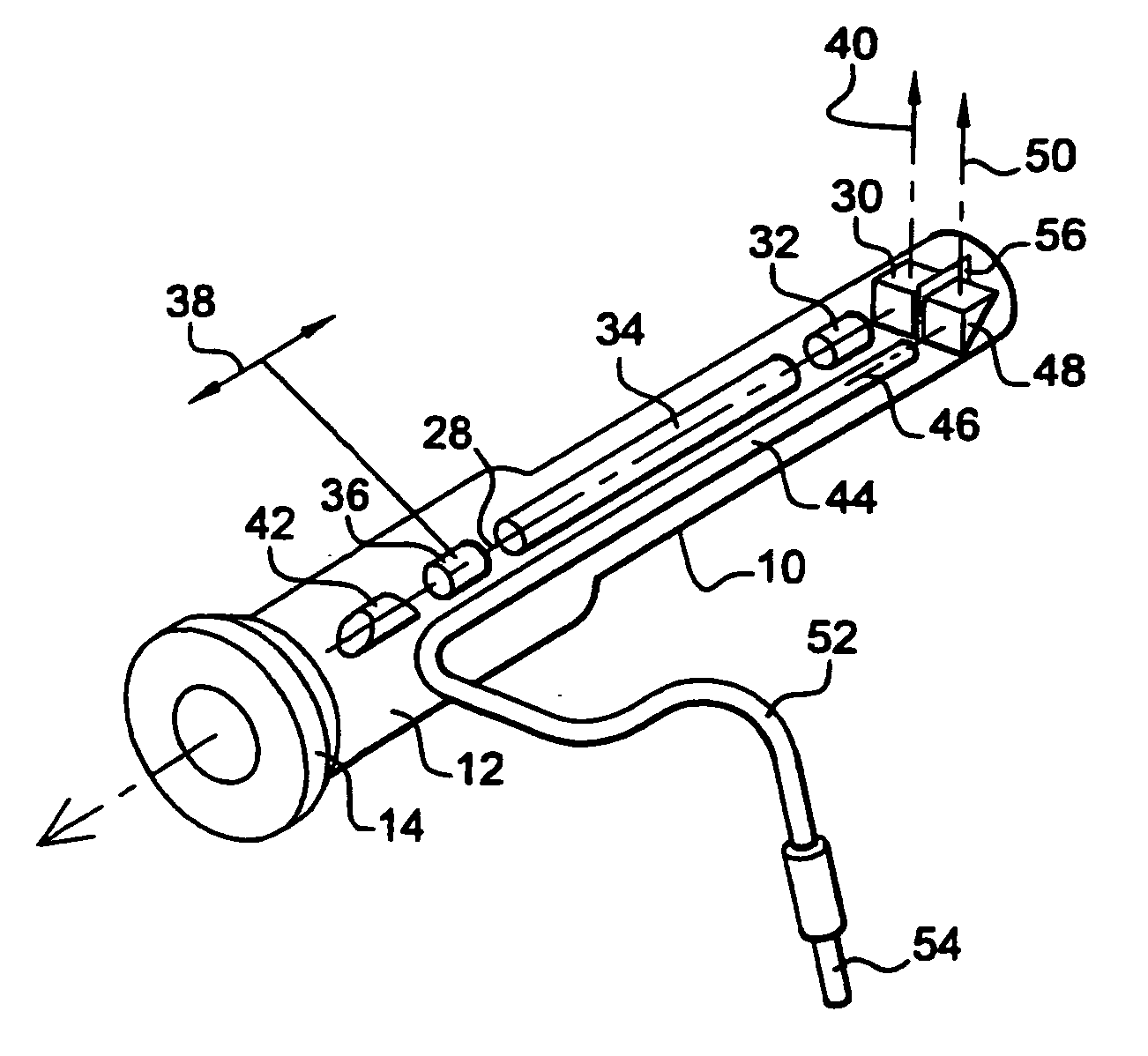
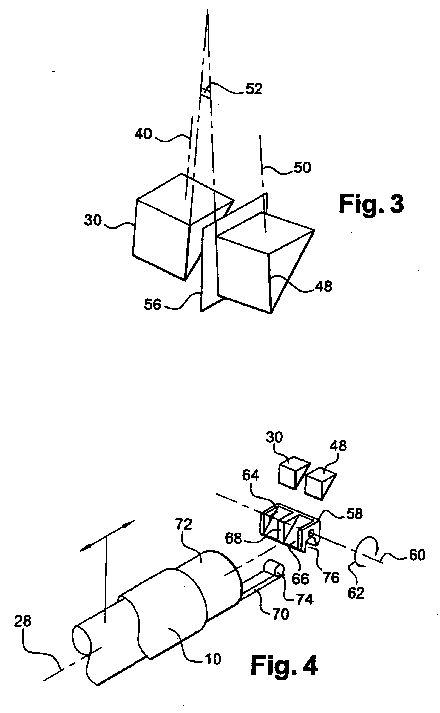
[0012] The transverse disposition of the two prisms side by side is compact and makes the endoscope easier to use.
[0014] This makes it possible to use light guide means which are not angled or bent.
[0017] This makes it possible to view forwards, sideways, or backwards, and to improve the conditions which objects for inspection can be observed.
[0019] It is also possible to make provision in the endoscope of the invention for the viewing axis and the lighting axis to converge substantially at a determined lateral distance from the endoscope tube in order to achieve better lighting and better observation of objects situated at said distance.

Problems solved by technology

Such lighting means are unsuitable for transmitting ultraviolet light as produced, for example, by a mercury vapor lamp; and in order to transmit ultraviolet radiation it is necessary to use fibers made of quartz or of a suitable plastics material, or indeed a liquid conductor (a sheath filled with an appropriate liquid that is transparent to ultraviolet radiation), such light conductors possessing a degree of rigidity and not enabling their distal ends to be bent with a radius of curvature that is small enough to enable them to be mounted in an endoscope.
However that solution is not very satisfactory because of the limited optical field and because of the degradation over time of the efficiency with which ultraviolet light is reflected by the mirror, dirt and mirror defects leading to losses of energy that do not enable an object to be illuminated with sufficient intensity and which impede observation by returning a fuzzy image of the illuminated object.

Method used


Image

  • Endoscope with ultraviolet illumination
  • Endoscope with ultraviolet illumination
  • Endoscope with ultraviolet illumination

Examples


Embodiment Construction

[0025] Reference is made initially to FIG. 1 which shows a prior art endoscope essentially comprising a rigid rectilinear tube 10 containing lighting means and observation means, the tube 10 having a proximal end forming a handle 12 and provided with an eyepiece cup 14, and a distal end 16 for inserting into a casing, e.g. via a small-diameter orifice therein.

[0026] The lighting means housed in the tube 10 comprise a light conductor 18, such as an optical fiber cable, having a proximal end mounted in a connection socket 20 carried by the handle 12 of the endpiece and designed to receive the end of a lighting cable 22 connected to a source of white light. The distal end 24 of the light conductor 18 has a bend, e.g. through substantially a right angle, thereby defining a lighting axis 26 which is inclined relative to the longitudinal axis 28 of the endoscope.

[0027] The observation means comprise a viewing prism 30 which is mounted on the longitudinal axis 28 of the endoscope at its ...


PUM


Abstract

An endoscope with deflected distal viewing, comprises a rigid tube containing observation means, themselves comprising a distal deflector prism having a viewing axis that is inclined relative to the axis of the tube, and ultraviolet light guide means housed in the tube and opening out at their distal end onto a prism for deflecting the illuminating light beam in a direction that is substantially parallel to the viewing axis. The invention applies in particular to inspecting parts by the penetration test technique in the aviation field.

Description

[0001] The invention relates to an endoscope with ultraviolet illumination and with deflected distal viewing intended in particular for observing defects presented by mechanical parts and shown up by using penetration test substances. [0002] The invention applies particularly, but not exclusively, to industrial endoscopy, in particular in the field of aviation, for visually inspecting internal parts that are difficult to access, such as, for example, the rotor blades of a turbojet or turboprop, by means of an endoscope which is caused to pass through an orifice of small diameter (e.g. 9 millimeters (mm)) which is provided for this purpose in the casing of the machine to be inspected, this technique presenting the advantage of not requiring total or partial prior disassembly of the machine. BACKGROUND OF THE INVENTION [0003] Endoscopes are known which are constituted essentially by a rigid probe for insertion into a dark cavity and fitted with means for illuminating an object to be i...

Claims


Application Information

Patent Timeline
IPC IPC(8): A61B1/00G01N21/84G01N21/91G02B23/24G02B23/26
CPCA61B1/00183A61B1/07A61B1/00188G02B23/2469A61B1/00096G02B23/2423
Inventor BONNINGUE, ISABELLELE QUELLEC, JOHNROVEGNO, JEAN
Owner SN DETUDE & DE CONSTR DE MOTEURS DAVIATION S N E C M A
Learn More