Freewheel flow track systems

a freewheel and track technology, applied in the direction of conveyor parts, rollers, roller-ways, etc., can solve the problems of low quality of pallets used in picking operations, low friction coefficient of steel wheel track systems, and wheel catching by broken boards, etc., to achieve high durability, low friction coefficient, and high rollability

Inactive Publication Date: 2005-04-14
CREATIVE STORAGE SYST
View PDF21 Cites 0 Cited by
  • Summary
  • Abstract
  • Description
  • Claims
  • Application Information

AI Technical Summary

Benefits of technology

[0009] A lubricant coating is fixed to and bonded with the axle. The polycarbonate resin wheels are constructed from a polycarbonate-based resin that is impregnated with a lubricant for providing lifetime lubrication to the wheels. The lubricant in the wheels and the lubricant coating of the axles give the wheel assemblies a low coefficient of friction, high rollability and high durability. The wheels each include a hub, a rim that is concentric with the hub, a web that connects the hub to the rim and ribs that connect the hub to the rim through the web. The wheel assemblies are self-lubricating and are of high strength for transporting heavy pallets and cartons.

Problems solved by technology

There are several problems that occur with existing steel wheel track systems.
One problem occurs because the pallets used in picking operations are sometimes low quality pallets that have broken bottom boards and / or soft, damaged wood.
Due to the narrowness of the steel wheels presently used (only 0.50 inches to 0.56 inches wide), the wheels tend to get caught by broken boards or embed themselves in soft wood.
Likewise, when damaged cartons are transported directly on a track assembly, the wheels tend to embed themselves in damaged sections of the cartons.
As a result, operators have slipped, fallen and sustained injuries while using shepherd's tools to move pallets.
Another problem occurs when low quality pallets are used.
However, the wheels are subjected to unusually high loads when a pallet is used that is missing a front or a back board, or that is otherwise shorter than the pallets the tracking system is designed to carry.
The wheels may not be capable of supporting the elevated loads and may break, requiring the picking operator to use a shepherd's tool to move the pallets forward along the track assembly.
As stated before, this can result in injury to the picking operator.
Yet another problem exists with present steel wheel track systems.
However, the steel wheels used in present flow track systems are susceptible to corrosion.
Thus, frequent washdowns can damage steel wheels and cap eventually render them inoperable.

Method used


Image

  • Freewheel flow track systems
  • Freewheel flow track systems
  • Freewheel flow track systems

Examples


Embodiment Construction

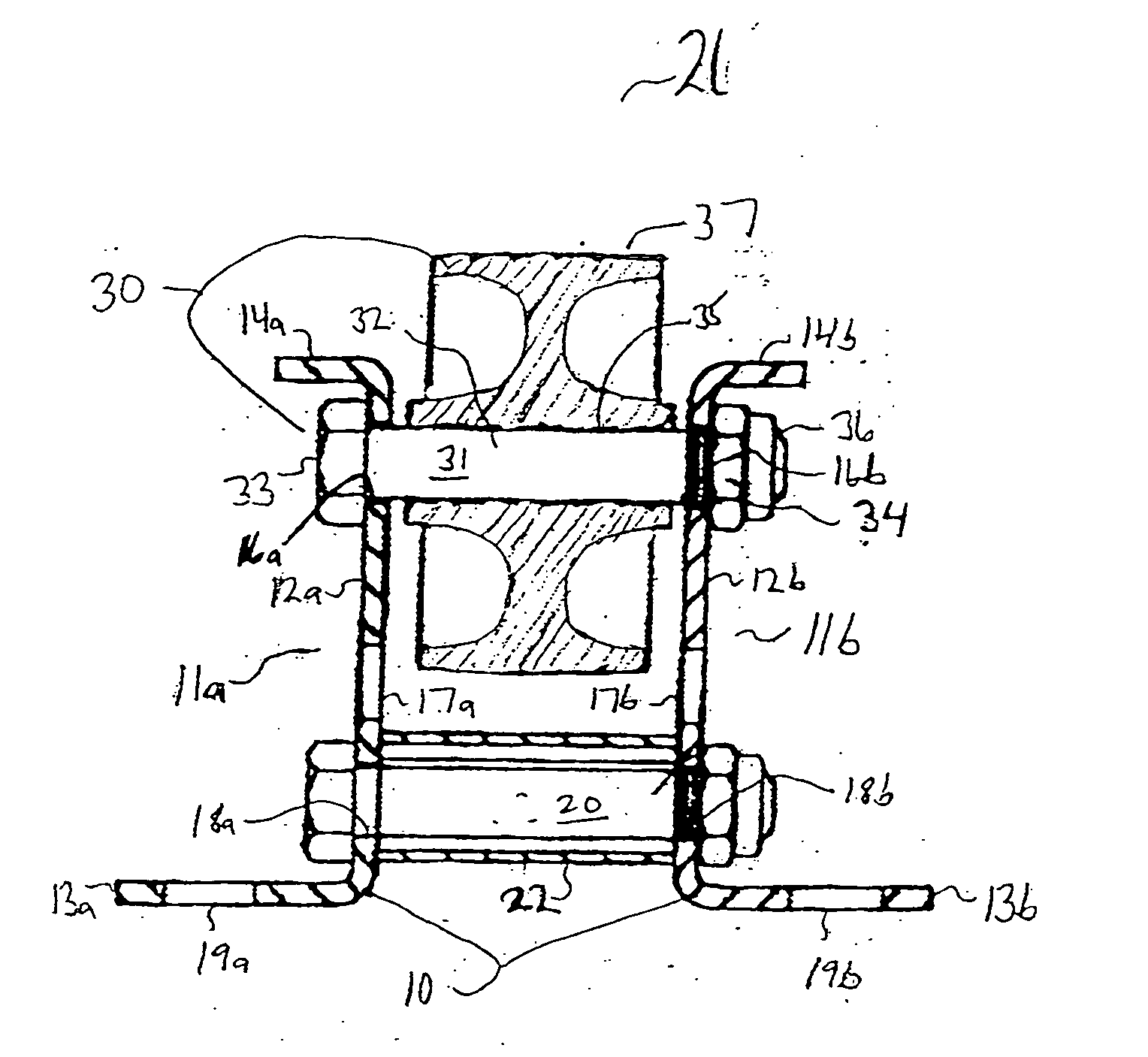
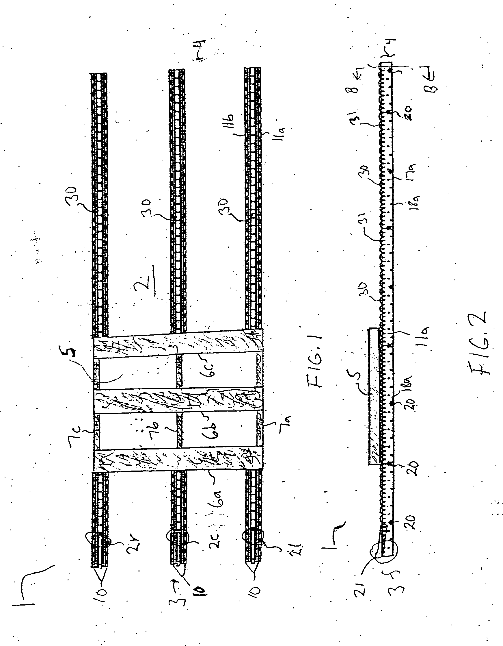
[0055] Referring to the drawings, in which like numerals represent like components throughout the several views, FIGS. 1 and 2 show cut-away representations of a Freewheel Flow Track System 1 according to a preferred embodiment of the invention. FIG. 1 shows a cutaway view of the freewheel flow track system 1 including a track assembly 2 having an entrance end 3 and an exit end 4. Products supported by the track assembly 2 are transported in a track flow direction extending from the entrance end 3 to the exit end 4. The track assembly 2 comprises three parallel track sub-assemblies 2l, 2c and 2r extending longitudinally from the entrance end 3 to the exit end 4, wherein the track sub-assemblies 2l, 2c and 2r are left, center and right sub assemblies, as viewed from exit end 4. It should be understood that, although the track system 1 is shown with three track sub-assemblies, it is possible for track systems to include fewer than three track sub-assemblies or more than three track su...


PUM


Abstract

Freewheel flow track systems for transporting pallets and / or cartons in heavy-duty pallet and carton flow applications are disclosed. According to certain embodiments of the invention, a flow track system comprising multiple longitudinally extending, parallel track sub-assemblies is disclosed. The track sub-assemblies each comprise multiple wheel assemblies mounted to a track frame and arranged in a row extending from an entrance end of the track assembly to an exit end of the track assembly. Each wheel assembly comprises an axle and a polycarbonate resin wheel rotatably mounted on the axle. A lubricant coating is fixed to and bonded with the axle. The wheel is constructed from a polycarbonate-based resin that is impregnated with a lubricant for providing lifetime lubrication to the wheels. The wheel includes a hub, a rim concentric with the hub, a web connecting the hub to the rim, and ribs connecting the hub to the rim through the web. According to other embodiments of the invention, a flow track system including a single track assembly is disclosed. The track assembly includes multiple wheel assemblies mounted on a track frame and arranged in a row extending from an entrance end of the track assembly to an exit end of the track assembly. In these embodiments, each wheel assembly includes an axle and multiple polycarbonate resin wheels rotatably mounted on the axle. The flow track systems disclosed by the invention have a high load capacity, and the wheel assemblies of the flow track systems have a low coefficient of friction, high rollability and high durability. Therefore, the freewheel flow track systems disclosed by the invention provide reliable, efficient and safe pallet and carton flow.

Description

[0001] This application claims the benefit of U.S. provisional application Ser. No. 60 / 234,568 filed on Sep. 22, 2000 and titled “Freewheel Flow Track System”.BACKGROUND OF THE INVENTION [0002] The steel wheel track system, or skate wheel track system, is one of the most commonly used flow track systems in the material handling industry. The steel wheel track system comprises a track assembly including one or more parallel track frames. Each track frame includes a pair of parallel steel frame members, also known as “profiles”, and multiple wheel assemblies mounted between the profiles. Each wheel assembly includes a steel wheel rotatably mounted on an axle that extends between the profiles transverse to the track flow direction. The wheels are typically 1.9 inches in diameter and 0.50 inches to 0.56 inches in width. The wheels comprise steel outer shells having thicknesses between 22 gage and 13 gage, depending upon the particular application in which the wheels are used. Additional...

Claims


Application Information

Patent Timeline
Patent Type & Authority Applications(United States)
IPC IPC(8): B65G13/00B65G39/12
CPCB65G39/12B65G13/00
Inventor LAWLESS, ROBERT J.
Owner CREATIVE STORAGE SYST
Why Eureka
Try Eureka