
Optical disk drive

a technology of optical disk drive and memory area, applied in the direction of memory address/allocation/relocation, instruments, recording signal processing, etc., can solve the problems of the chance of a cache hit being found in the first memory area and the chance of a cache hit being found in the second memory area, and achieve the effect of increasing the read ra

Inactive Publication Date: 2005-03-31
TEAC CORP
View PDF8 Cites 17 Cited by
  • Summary
  • Abstract
  • Description
  • Claims
  • Application Information

AI Technical Summary

Benefits of technology

[0010] The present invention provides an optical disk drive capable of increasing a read rate when data are read from an optical disk.
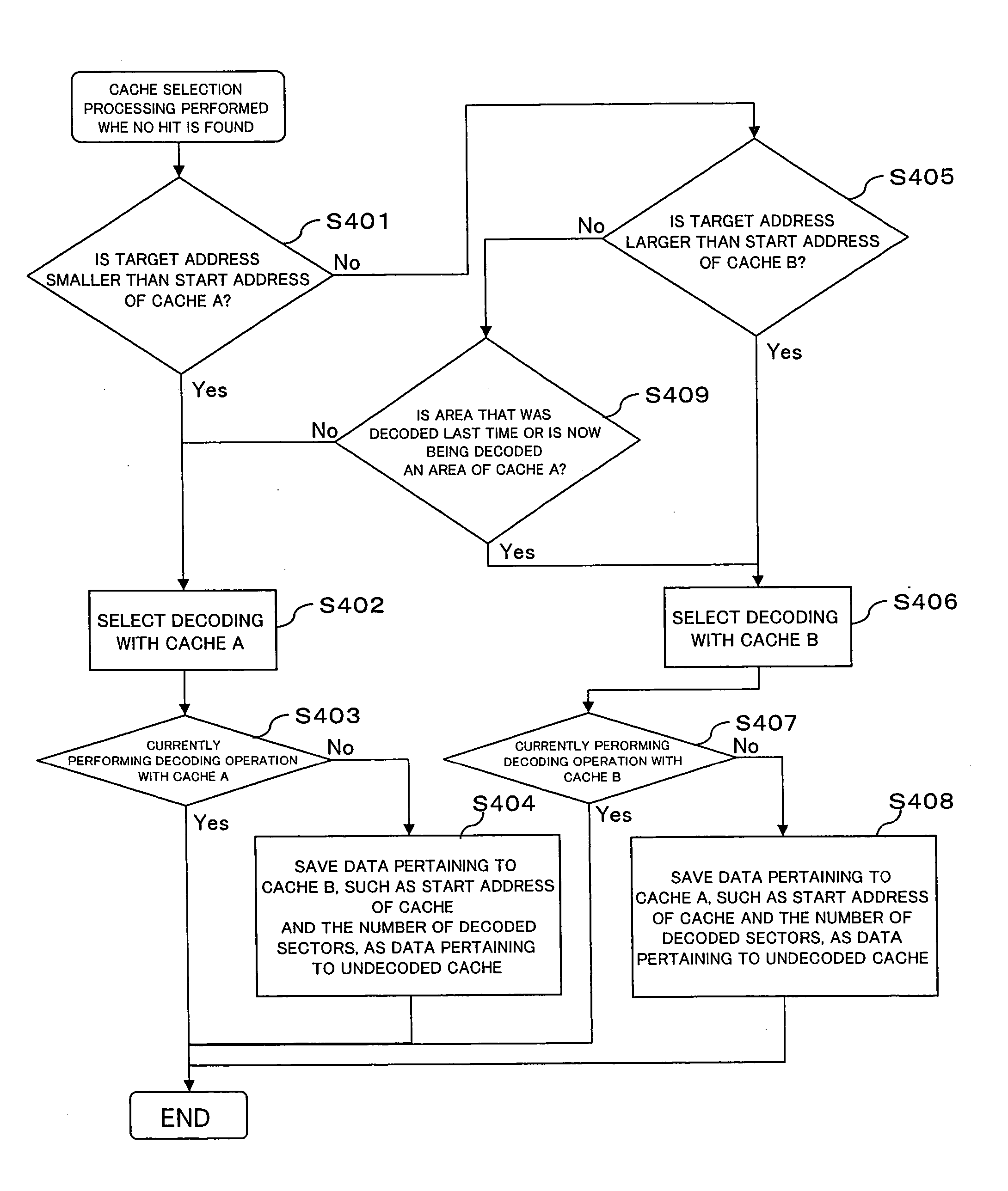
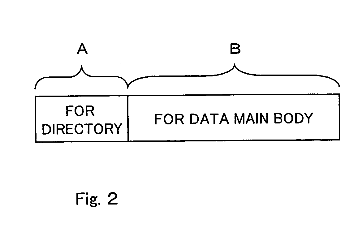
[0012] File management data, such as directory data or the like, are chiefly stored in the first memory area, and file data are chiefly stored in the second memory area. Even when the directory data and the file data are alternately read, a cache hit rate is improved. Specifically, when the directory data are requested, there is a chance of a cache hit being found in the first memory area. Subsequently, when the file data are requested, there is a chance of a cache hit being found in the second memory area. Even when the read data are written in the second memory area, the file management data stored in the first memory are a are not affected. Even when the directory data are again requested, the chance of a cache hit being found in the first memory area is maintained.
[0013] In an embodiment of the present invention, the second memory area is larger in storage capacity than the first memory area. This is because the file data are larger than the file management data. As a result of the file data being written into the second memory area having large storage capacity, the volume of file data read in advance is increased, thereby increasing a cache hit rate.

Problems solved by technology

Specifically, when the directory data are requested, there is a chance of a cache hit being found in the first memory area.
Subsequently, when the file data are requested, there is a chance of a cache hit being found in the second memory area.

Method used


Image

  • Optical disk drive
  • Optical disk drive
  • Optical disk drive

Examples


Embodiment Construction

[0033] An embodiment of the present invention will be described hereinbelow by reference to the drawings.

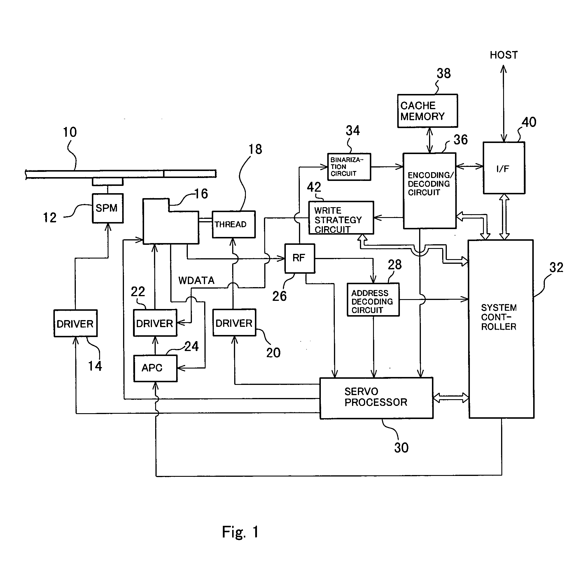
[0034]FIG. 1 shows a block diagram of the entirety of an optical disk drive according to an embodiment of the present invention. An optical disk 10, such as a DVD-ROM, DVD-RW, or DVD-RAM, is rotationally driven by a spindle motor (SPM) 12. The spindle motor SPM12 is driven by a driver 14, and the driver 14 is servo-controlled by a servo processor 30 such that a desired rotational speed is achieved.

[0035] An optical pickup 16 includes a laser diode (LD) for radiating a laser beam on the optical disk 10, and a photodetector (PD) which receives light reflected from the optical disk 10 and converts the thus-received light into an electrical signal. The optical pickup 16 is disposed opposite the optical disk 10. The optical pickup 16 is driven in a radial direction of the optical disk 10 by a thread motor 18, and the thread motor 18 is driven by a driver 20. Like the driver 14, the ...


PUM

PropertyMeasurementUnit
radiusaaaaaaaaaa
sizeaaaaaaaaaa
inner radiusaaaaaaaaaa

Abstract

An optical disk drive which increases a read rate when a read command from a host system is input. Data read from the optical disk drive are buffered in cache memory, and requested data are subsequently transferred to a host system. The cache memory is divided into cache A and cache B. Directory data are chiefly buffered in the cache A, and file data are chiefly buffered in the cache B. A cache hit rate achieved when the directory data and the file data are alternately read is improved.

Description

FIELD OF THE INVENTION [0001] The present invention relates to an optical disk drive, and more particularly, to cache memory for temporarily storing data read from an optical disk. DESCRIPTION OF THE RELATED ART [0002] When data are read from an optical disk, such as a CD or a DVD, cache memory is used for increasing a read rate. Specifically, when a read command is input from a host system, such as a personal computer (PC) or the like, a controller of an optical disk drive transfers the data read from the optical disk to the host system after having temporarily stored the data in the cache memory, rather than transferring the data directly to the host system. Even when another read command pertaining to the same data is input, the data can be transferred from the cache memory without accessing the optical disk to read the data, and therefore the read rate is increased. In order to improve a hit rate of the cache memory, there has been adopted a method for reading, in advance, requi...

Claims


Application Information

Patent Timeline
Patent Type & Authority Applications(United States)
IPC IPC(8): G06F3/06G06F12/00G06F12/08G11B20/10G11B27/00G11B27/10G11B27/11G11B27/24
CPCG06F12/0871G11B2220/65G06F2212/2146G06F2212/282G06F2212/466G11B20/10527G11B27/005G11B27/105G11B27/11G11B27/24G11B2020/10675G11B2020/10759G11B2220/216G11B2220/2545G11B2220/2562G11B2220/2575G06F2212/211
Inventor MIYAMOTO, TAKASHI
Owner TEAC CORP
Learn More