
Ramp voltage generating apparatus and active matrix drive-type display apparatus

a technology of active matrix and display apparatus, which is applied in the direction of pulse generator, pulse technique, instruments, etc., can solve the problems of increasing effect, complicated circuit configuration, and 84 horizontal lines for each horizontal line, so as to reduce the influence of voltage drop on the power line and simplify the circuit configuration

Inactive Publication Date: 2005-03-31
SANYO ELECTRIC CO LTD
View PDF6 Cites 30 Cited by
  • Summary
  • Abstract
  • Description
  • Claims
  • Application Information

AI Technical Summary

Benefits of technology

[0032] Accordingly, it is an object of the present invention to provide a ramp voltage generating apparatus and an active matrix drive-type display apparatus having a simple circuit configuration capable of generating a plurality of ramp voltages out of phase with each other.

Problems solved by technology

In the case where the scanning speed is low, the luminescence period is so short that an excessive peak current flows in the organic EL element, thereby increasing the effect of the voltage drop of the power line in the display panel.
In the organic EL display apparatus shown in FIG. 17, however, the provision of the D / A converter 82 for each horizontal line and the delay circuit 81 for each of the second to last lines poses the problem that the circuit configuration is complicated.
Nevertheless, the provision of the low-pass filter 84 for each horizontal line complicates the circuit configuration of this organic EL display apparatus.

Method used


Image

  • Ramp voltage generating apparatus and active matrix drive-type display apparatus
  • Ramp voltage generating apparatus and active matrix drive-type display apparatus
  • Ramp voltage generating apparatus and active matrix drive-type display apparatus

Examples


first embodiment

[0085] An organic EL display apparatus according to a first embodiment of the present invention will be described specifically with reference to the drawings.

[0086] (FIG. 1: Block Diagram of General Configuration)

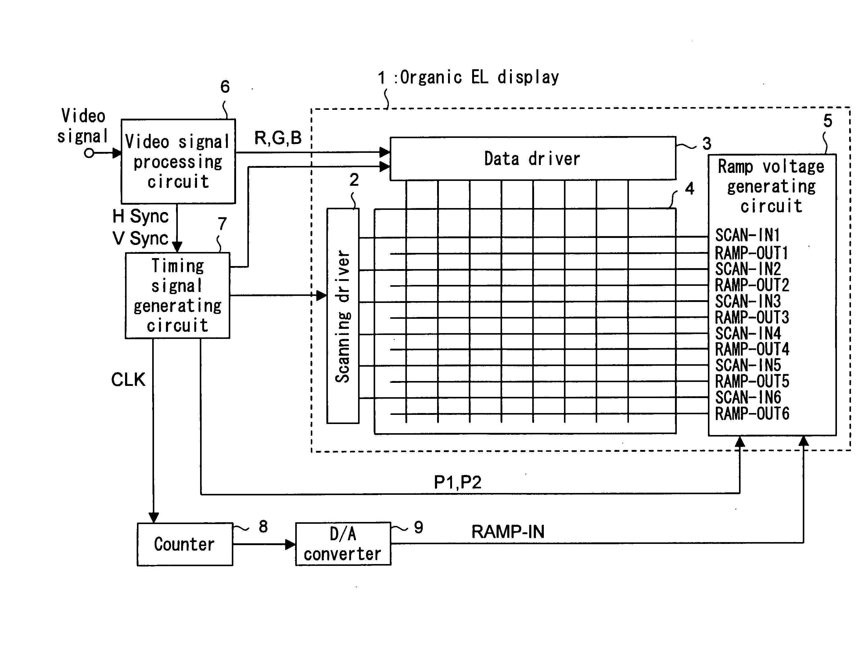
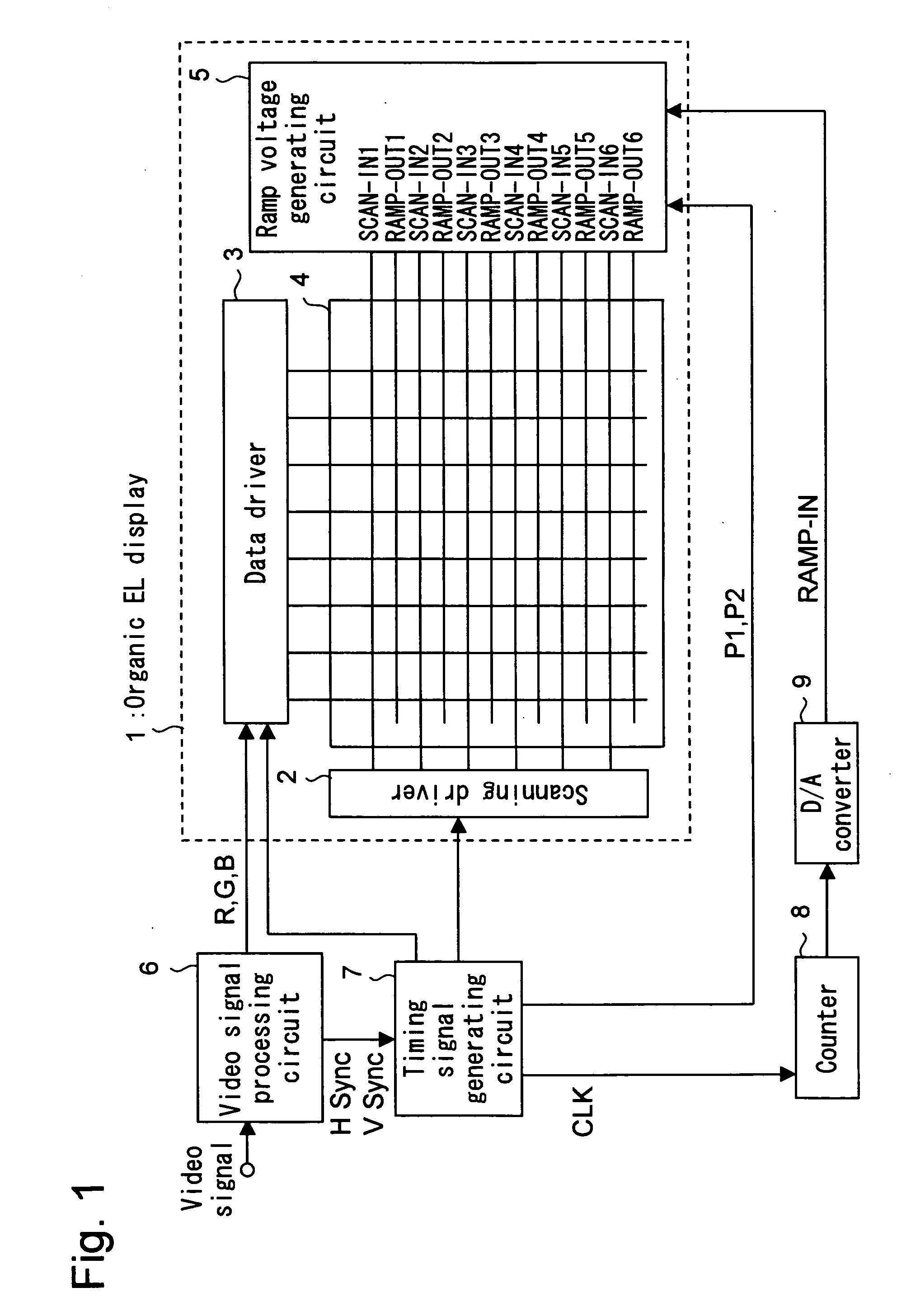
[0087]FIG. 1 is a block diagram showing a general configuration of the organic EL display apparatus according to the first embodiment of the present invention. An organic EL display 1, as shown in FIG. 1, includes a display panel 4 with a plurality of pixels arranged in matrix, to which a scanning driver 2, a data driver 3 and a ramp voltage generating circuit 5 are connected.

[0088] A video signal supplied from a video source such as a TV receiver (not shown) is supplied to a video signal processing circuit 6 and is processed as required for video display. The resulting video signals of RGB primary colors are supplied to the data driver 3 of the organic EL display 1.

[0089] A horizontal sync (synchronizing) signal Hsync and a vertical sync signal Vsync obtained from the ...

second embodiment

[0121] Next, an organic EL display apparatus according to a second embodiment of the present invention will be described specifically with reference to the drawings.

[0122] (FIG. 6: Block Diagram of General Configuration)

[0123]FIG. 6 is a block diagram showing a general configuration of the organic EL display apparatus according to a second embodiment of the present invention. In FIG. 6, the component parts identical or similar to the corresponding component parts in FIG. 1 are designated by the same reference numerals, respectively, and not described again. An organic EL display 21, as shown in FIG. 6, includes a display panel 24 with a plurality of pixels arranged in matrix thereon, a scanning driver 2, a data driver 3 and a ramp voltage generating circuit 25. Though not shown in FIG. 6, the organic EL display 21 further includes a set-up voltage control circuit 57 (FIG. 7).

[0124] As in the first embodiment, the count obtained from the counter 8 is supplied to the D / A converter ...


PUM


Abstract

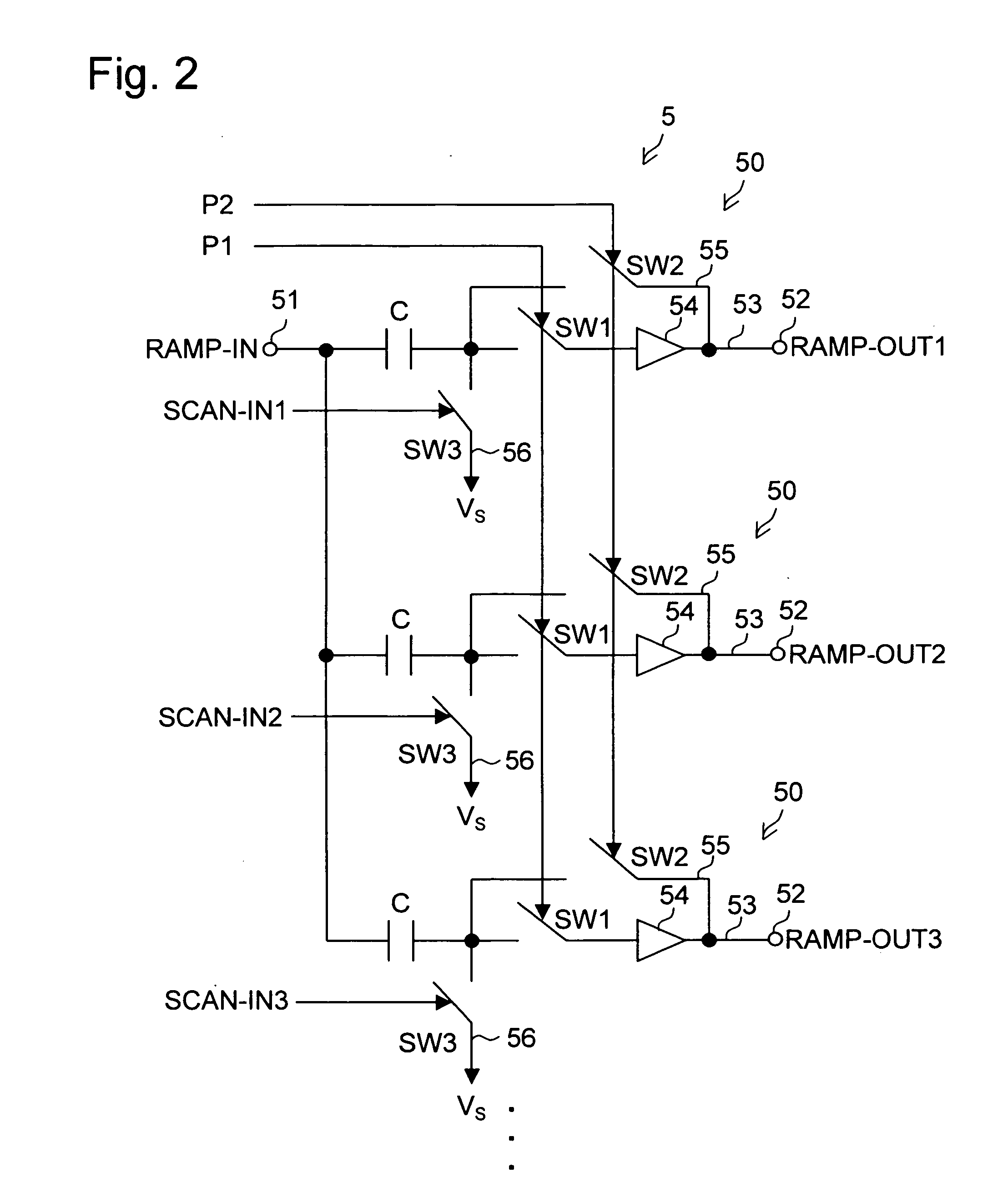
A ramp voltage generating apparatus according to the present invention includes a ramp voltage generating circuit for generating a plurality of ramp voltages out of phase with each other from one ramp voltage, and a control circuit. The ramp voltage generating circuit includes a plurality of voltage generating circuit portions connected in parallel to a voltage input terminal. Each voltage generating circuit portion includes a voltage output terminal, a capacitor, an operational amplifier, a first switch, a second switch and a third switch. The control circuit turns on the third switches while shifting the time point of switching each of the third switches from off to on state, and the control circuit turns off the first switches and, also, turns on the second switches during the period including the fall time point of the ramp voltage input to the voltage input terminal.

Description

[0001] This application is based on Japanese Patent Application No. 2003-338241 filed on Sep. 29, 2003 and Japanese Patent Application No. 2004-094813 filed on Mar. 29, 2004, the contents of which are hereby incorporated by reference. BACKGROUND OF THE INVENTION [0002] 1. Field of the Invention [0003] The present invention relates to a ramp voltage generating apparatus having a ramp voltage generating circuit for generating a plurality of ramp voltages out of phase with each other, and an active matrix drive-type display apparatus. [0004] 2. Description of the Prior Art [0005] In recent years, an organic electroluminescence display (hereinafter, referred to as “organic EL display”, and a display apparatus using the organic EL display as “organic EL display apparatus”) has been under development. Use of the organic EL display for a mobile telephone, for example, is being studied. [0006] As a method of driving the organic EL display, there have been known a passive matrix drive type f...

Claims


Application Information

Patent Timeline
IPC IPC(8): G09G3/20G09G3/30H01L51/50G09G3/32H03K4/02H03K4/08H03K4/501H03K17/00H05B33/14H05B37/02H05B41/36H05B44/00
CPCG09G3/2014G09G3/3258G09G3/3266G09G2320/043G09G2310/066G09G2320/02G09G2320/029G09G2300/0842
Inventor YAMASHITA, ATSUHIRO
Owner SANYO ELECTRIC CO LTD
Learn More