
Method and device for coating a substrate

a technology of coating and substrate, applied in the direction of electric/magnetic/electromagnetic heating, magnetic bodies, transportation and packaging, etc., can solve the problems of limited transfer rate, significant proportion of heat supplied loss, and limited use of ceramic crucibles

Inactive Publication Date: 2005-03-24
TATA STEEL NEDERLAND TECH BV
View PDF11 Cites 30 Cited by
  • Summary
  • Abstract
  • Description
  • Claims
  • Application Information

AI Technical Summary

Benefits of technology

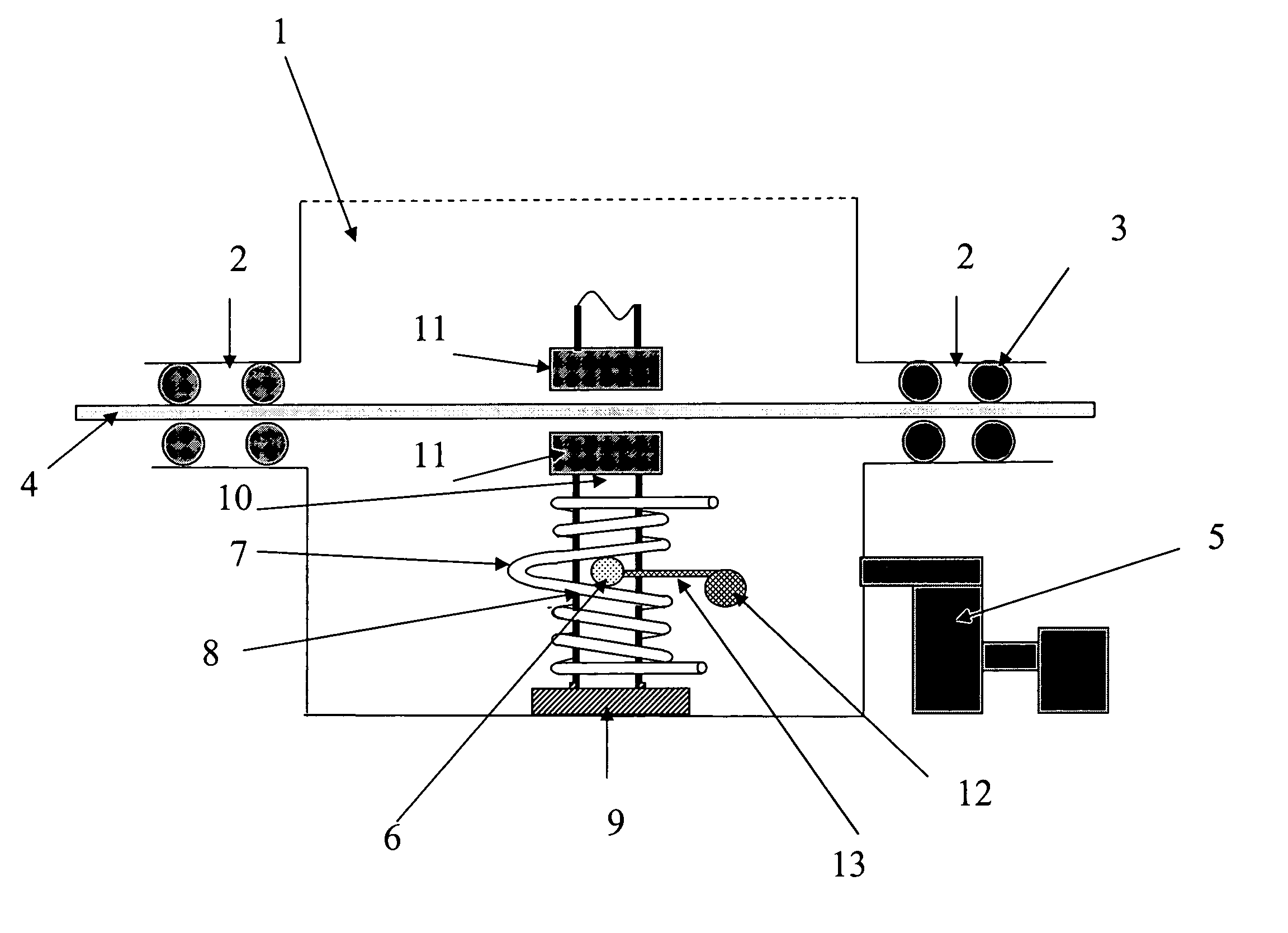
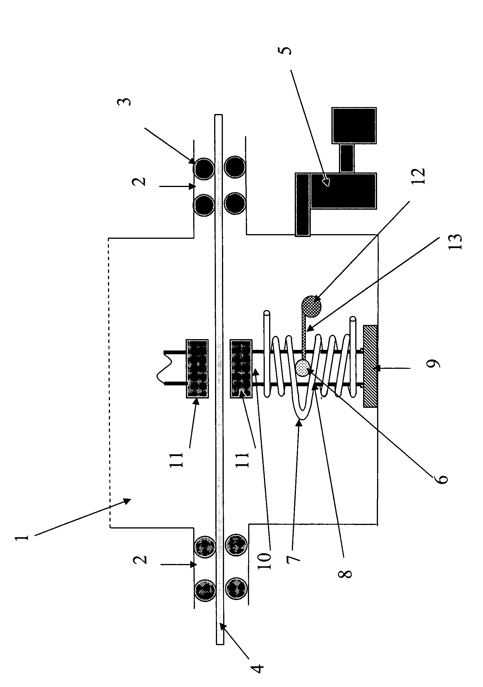
[0014] Keeping the material which is to be vaporized floating without support in the space means that it is no longer necessary to use a copper or ceramic crucible. As a result, it is possible to impart a higher temperature to the material which is to be vaporized, since the crucible no longer forms the limiting factor. Therefore, the transfer rate of the vaporized material to the substrate can be increased. Since it is no longer necessary to use a crucible, it is also possible to vaporize materials which it has not hitherto been possible to use, on account of their ability to react with the material of the crucible.

Problems solved by technology

Metals such as tantalum, molybdenum and tungsten require such high temperatures that they are not used for PVD.
A drawback of using PVD is that the transfer rates are limited primarily by the fact that the coating materials which have to be vaporized are always in the liquid state on account of the high process temperatures.
One disadvantageous consequence of cooling of a copper crucible is that a significant proportion of the heat supplied is lost as a result of the cooling.
The use of a ceramic crucible is limited to coating materials which do not enter into a chemical reaction with the crucible material at the high process temperatures.
The supply of the thermal energy required also presents a problem when using a ceramic crucible, since most ceramic materials are poor heat conductors.

Method used


Image

  • Method and device for coating a substrate
  • Method and device for coating a substrate

Examples


Embodiment Construction

[0013] According to a first aspect of the invention, one or more of these objects are achieved by a method for coating a substrate with a layer of a material, such as a metal, to form a coated substrate. In the method a quantity of electrically conductive material is vaporized in a chamber providing a space with a low background pressure and energy is supplied to the material which is to be vaporized in order to vaporize this material. In this method the material which is to be vaporized, while it is being vaporized, is kept floating, without support, in the space and is enclosed in an alternating electromagnetic field, and in which method the alternating electromagnetic field is generated with the aid of a high-frequency alternating current. Typically the chamber communicates with a vacuum pump to achieve the low background pressure.

[0014] Keeping the material which is to be vaporized floating without support in the space means that it is no longer necessary to use a copper or cer...


PUM

PropertyMeasurementUnit
Poweraaaaaaaaaa
Currentaaaaaaaaaa
Frequencyaaaaaaaaaa

Abstract

The invention relates to a method for coating a substrate with a layer of a material, such as a metal, in which a quantity of electrically conductive material is vaporized in a space with a low background pressure and energy is supplied to the material which is to be vaporized in order to vaporize this material. According to the invention, the material which is to be vaporized, while it is being vaporized, is kept floating, without support, in the space and is enclosed in an alternating electromagnetic field, the alternating electromagnetic field being generated with the aid of a high-frequency alternating current. The invention also relates to a device for coating a substrate and to a substrate.

Description

CROSS-REFERENCE TO RELATED APPLICATIONS [0001] This application is a continuation-in-part of International Application No. PCT / NL03 / 00139, filed on 21 Feb. 2003, claiming the priority of Netherlands Patent Application No. 1020059 filed on 21 Feb. 2002, both of which are incorporated herein by reference in their entirety.FIELD OF THE INVENTION [0002] The invention relates to a method for coating a substrate with a layer of a material, such as a metal, in which a quantity of electrically conductive material is vaporized in a space with a low background pressure and energy is supplied to the material which is to be vaporized in order to vaporize this material. The invention also relates to a device for coating a substrate, and to a substrate obtained using the method or device. BACKGROUND OF THE INVENTION [0003] The method described above is a known technique for coating substrate with (thin) layers of coating material; the method is usually referred to as physical vapour deposition (P...

Claims


Application Information

Patent Timeline
IPC IPC(8): C23C14/24
CPCC23C14/24C23C14/16Y10T428/31678
Inventor SCHADE VAN WESTRUM, JOHANNES ALPHONSUS FRANCISCUSGLEIJM, GERARDUS
Owner TATA STEEL NEDERLAND TECH BV
Learn More