
Chair

Inactive Publication Date: 2005-03-24
DICKS GERALD G
View PDF20 Cites 165 Cited by
  • Summary
  • Abstract
  • Description
  • Claims
  • Application Information

AI Technical Summary

Benefits of technology

[0005] A chair for commercial use has improved features in accordance with the inventions that provide for user flexibility as well as ergonomic enhancements that go beyond conventional mid back lumbar support and headrests. This chair has features that separate it from an everyday office chair.
[0012] The chair can provide a detachable headrest that adjust up and down providing comfort for almost any height person. The headrest can also provide adjustable side wings designed to provide side-to-side support. In addition this headrest provides a fully breathable substructure and is covered with breathable fabric designed to provide cool comfort for the back and sides of the head.
[0014] The chair may be equipped with a fully integrated plug-and-play LED lighting system designed to provide constant lighting even as the chair moves. This lighting system is powered by a hidden rechargeable battery and can easily provide light for up to 12 hours before recharging. The light is flexible and is located to illuminate an area in front of an occupant of the chair which the occupant needs to have illuminated, such as a reading area. The light is preferably attached removably to a connector on the upper back of the chair but it can be located in other suitable locations. The light is preferably a low temperature LED light which requires low wattage and enjoys long life. Low voltage helps maintain safety.

Problems solved by technology

Chairs, particularly work chairs, office chairs, and other commercial chairs in which occupants spend extensive time, can cause considerable discomfort.
They can be hot and they can provide inadequate or improper support.
In addition, chairs are usually not designed to accommodate people of different sizes, even though many prior art chairs are adjustable in regard to the height between the seat and the floor.

Method used


Image

  • Chair
  • Chair
  • Chair

Examples


Embodiment Construction

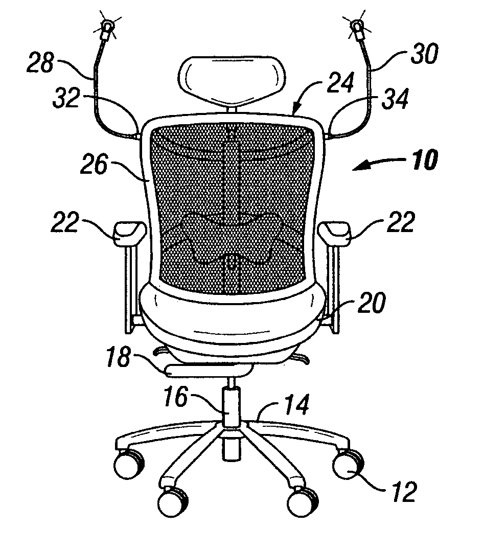
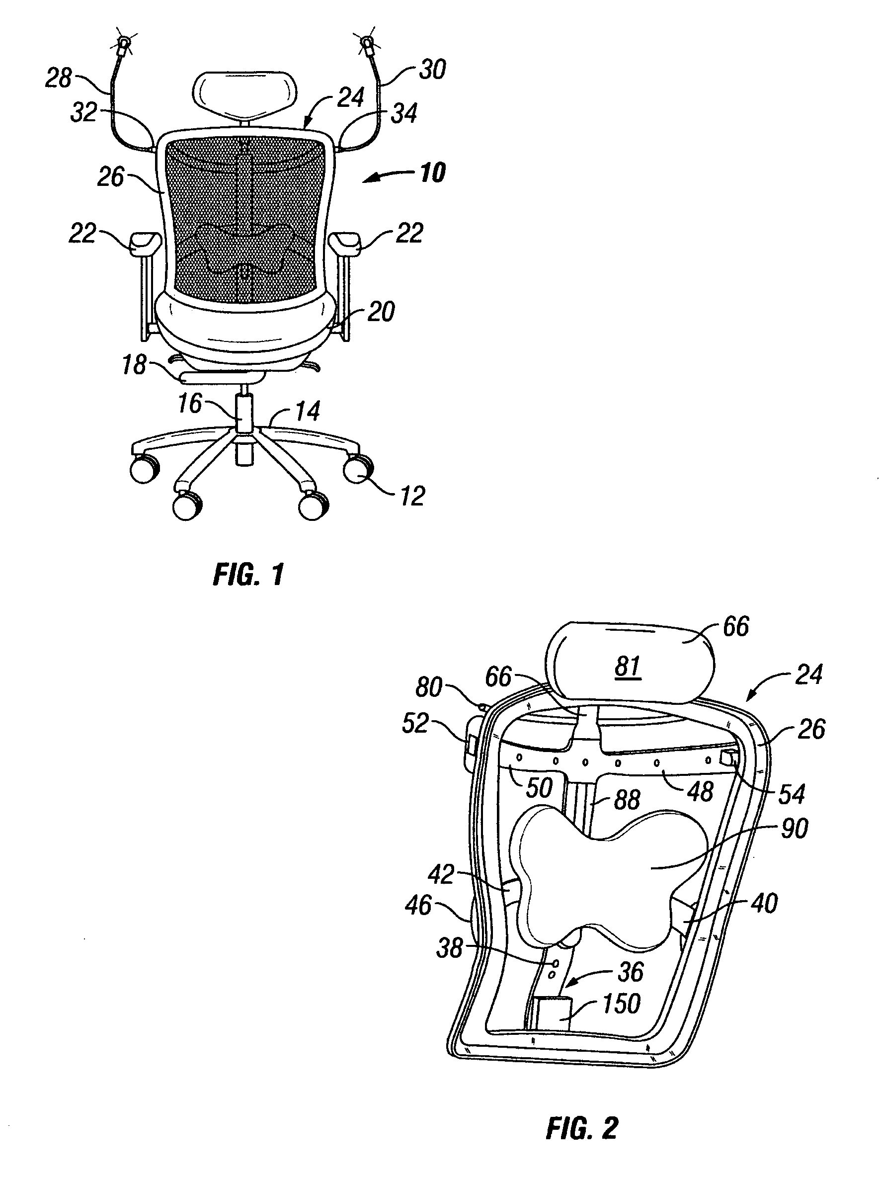
[0038] With reference to FIG. 1, a chair 10 is shown with casters 12 attached on a five-star base 14 which is connected to a central vertical post 16 having a gas lift height adjusting mechanism 18. A threaded mechanism can also work. The central post supports a swivel-tilt mechanism (not shown) that supports a seat 20 with arms 22. All of these components are well known in the art although modifications can be made as the art progresses.

[0039] The chair 10 includes a chair back 24 having a frame 26 with a back fabric 28 such as breathable mesh attached to and supported by the frame 26. Frame 26 is preferably shaped to support the back of an occupant.

[0040] The chair may also include one or more flexible lights 28 and 30 having electrical connectors 32 and 34 plugged into electrical connectors associated with the frame 26.

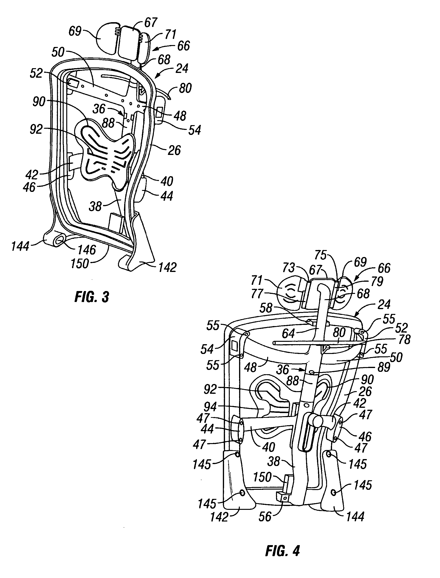
[0041] With reference to FIGS. 2, 3 and 4 the chair back 24 comprises frame 26 mounted on a lumbar base structure 36 which provides structural support to the fr...


PUM


Abstract

A back for an office chair comprises a peripheral frame shaped generally to outline the back of an occupant in the chair; a lumbar base structure attached to the frame; and a lumbar back support for an occupant of the chair connected to the lumbar base structure and extending toward the lumbar area of an occupant through an adjustable connection. The adjustable connection helps to provide comfort to the occupant and comprises one or more of a detent to allow adjustment of the height of the back support in relation to the frame, a movable joint to allow rotary motion of the lumbar back support in relation to movement of the back of the occupant, and an extensible connection to allow adjustment of the distance between the lumbar base structure and the lumbar back support. The chair back may also comprise at least one movable and flexible LED light supported by the back for reading comfort and may contain electrical circuitry to supply power to the LED light. The light may be removable with an electrical plug-in connection.

Description

RELATED APPLICATIONS [0001] This application claims priority on provisional application No. 60 / 477,504 filed Jun. 11, 2003 by Gerald G. Dicks, Houston, Tex.BACKGROUND OF THE INVENTION [0002] Chairs, particularly work chairs, office chairs, and other commercial chairs in which occupants spend extensive time, can cause considerable discomfort. They can be hot and they can provide inadequate or improper support. In addition, chairs are usually not designed to accommodate people of different sizes, even though many prior art chairs are adjustable in regard to the height between the seat and the floor. [0003] The inventions relate to an improved chair, particularly an office (commercial) chair, which provides improved features to enhance the use and enjoyment by an occupant. [0004] The improvements of the inventions set forth herein relate to, but are not limited to, chairs like those described in U.S. Design Patents D453,079 S and D446,411 S, which issued on Jan. 29, 2002, and Aug. 14, ...

Claims


Application Information

Patent Timeline
IPC IPC(8): A47C7/00A47C7/38A47C7/40A47C7/46
CPCA47C7/38A47C7/46A47C7/402A47C7/462
Inventor DICKS, GERALD G.
Owner DICKS GERALD G
Learn More