
Electrolytic capacitor with a thin film fuse

Inactive Publication Date: 2007-05-17
AVX CORP
View PDF36 Cites 20 Cited by
  • Summary
  • Abstract
  • Description
  • Claims
  • Application Information

AI Technical Summary

Benefits of technology

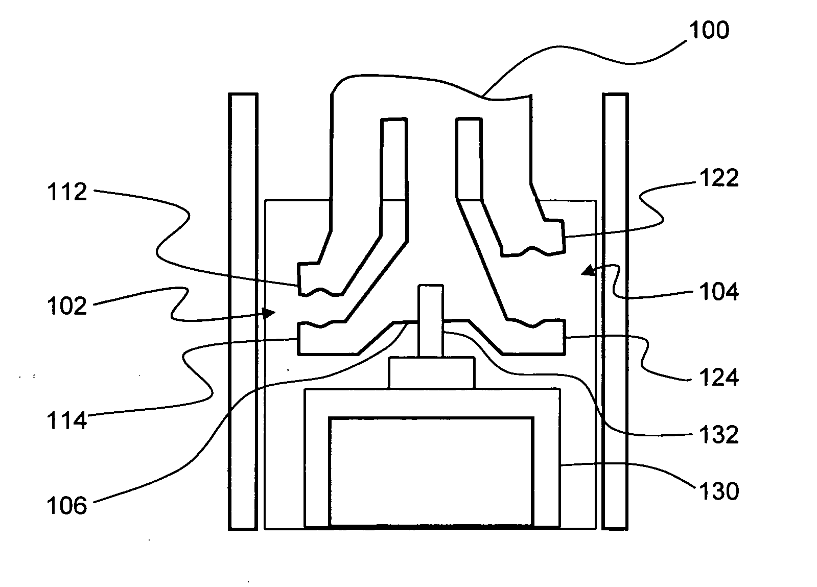
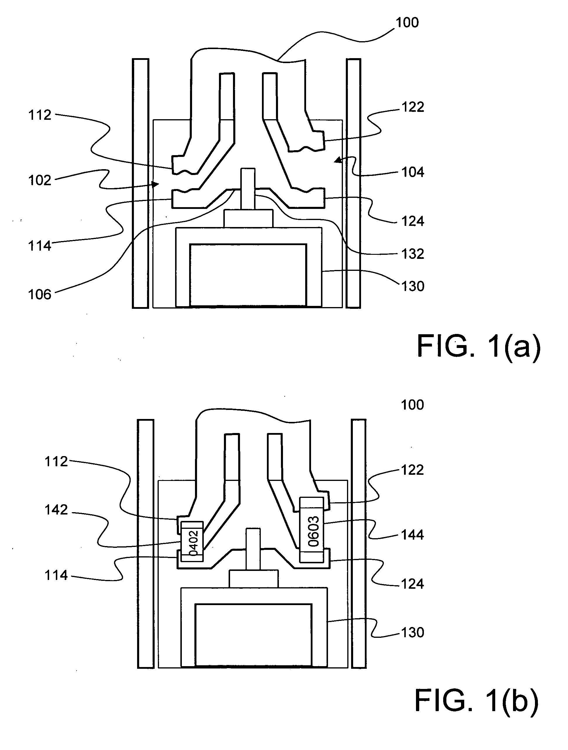
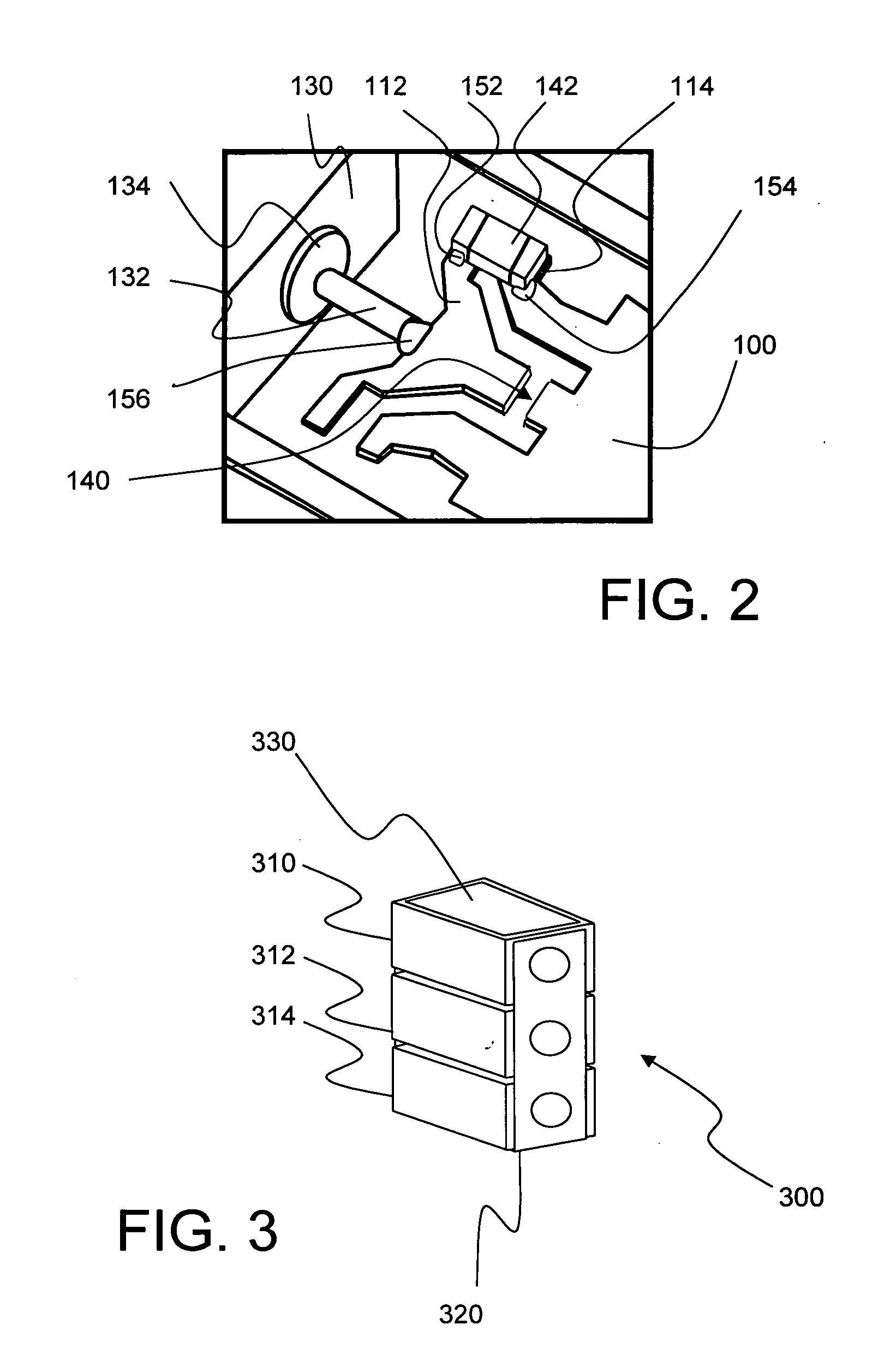
[0009] Another aspect of additional embodiments of the present technology is to provide a leadframe for an electrolytic capacitor with improved fuse link accommodating features. Such improved fuse link accommodating features enables certain embodiments of the present technology to provide variations in fuse capacity for various final products produced using the same leadframe.

Problems solved by technology

The prevalent desire to provide fusible protective features has, however, raised other issues including unintended increases in the overall equivalent series resistance (ESR) of the finished devices.
In addition, the prior art devices have provided capability for only fixed or single fuse values for the finished devices.
While examples of various aspects and alternative embodiments are known in the field of fused electrolytic capacitors, no one design has emerged that generally encompasses all of the above-referenced and other preferred capacitor characteristics.

Method used


Image

  • Electrolytic capacitor with a thin film fuse
  • Electrolytic capacitor with a thin film fuse
  • Electrolytic capacitor with a thin film fuse

Examples


Embodiment Construction

[0019] The present subject matter is particularly concerned with electrolytic capacitor technology. More particularly, the present technology provides an improved electrolytic capacitor with fusible features that contribute to a low Equivalent Series Resistance (ESR).

[0020] Selected combinations of aspects of the disclosed technology correspond to a plurality of different embodiments of the present invention. It should be noted that each of the exemplary embodiments presented and discussed herein should not insinuate limitations of the present subject matter. Features or steps illustrated or described as part of one embodiment may be used in combination with aspects of another embodiment to yield yet further embodiments. Additionally, certain features may be interchanged with similar devices or features not expressly mentioned which perform the same or similar function.

[0021] Reference will now be made in detail to the presently preferred embodiments of the subject fused electroly...


PUM


Abstract

The present technology relates to fused capacitor structures provided with a leadframe design configured to accepting a plurality of selectively placed fuses. The leadframe and fuse configuration enables construction of fused capacitors exhibiting low Equivalent Series Resistance (ESR) and allows construction of a variety of fuse configuration using a single leadframe design.

Description

BACKGROUND OF THE INVENTION [0001] Electrolytic capacitors, such as tantalum capacitors, are traditionally known for their high capacitance value and compactness. Typical components of a conventional electrolytic capacitor include a main capacitor body, an anode wire or body, an electrolyte, a cathode and a leadframe all molded together in an encapsulating resin package. The anode wire and leadframe of such capacitors form respective positive and negative electrical connections to the capacitor structure. In certain instances, the conduction path associated with the anode lead incorporates fusible protective aspects in the overall capacitor structure. [0002] A known interest in providing tantalum and other types of electrolytic capacitors with internal protective fuses has been previously addressed. U.S. Pat. No. 5,011,067 (Foisy) entitled “Method For Attaching A Fuse Wire To A Leadframe” discloses a tinned nickel-iron alloy lead frame having a plurality of pairs of extending tab po...

Claims


Application Information

Patent Timeline
IPC IPC(8): H02B1/00
CPCH01G2/16H01G9/012H01G9/042
Inventor EDSON, DOUGLAS MARKFIFE, JAMES ALLENVAILLANCOURT, GLENN MAURICEWADLER, DAVID ALLEN
Owner AVX CORP
Learn More