
Airvest human body cooling apparatus

Active Publication Date: 2005-03-17
HORN STEPHEN T
View PDF5 Cites 8 Cited by
  • Summary
  • Abstract
  • Description
  • Claims
  • Application Information

AI Technical Summary

Benefits of technology

[0009] Safety regulations require no more than 30 psi be directed toward the skin and with a thin inside mesh as might be used this can be easily exceeded. The present mesh possibly protects against this pressure by its strength, coarseness and thickness as well as the wavy pattern the fibers create and keeps the holes in the tubing off the wearer but in order to use a less expensive material changes to the existing vest are necessary. If a material is used that can seal to the skin like a perforated polyethylene then particles of sand could penetrate the skin.
[0012] The invention envisioned to correct these cooling efficiency and safety problem is to seal the outside of the vest with a wind resistant covering such as taffeta or a like material. Wind resistant material is any cloth where the space between the threads is proportionally smaller than the threads themselves as compared to a mesh material. A wind resistant material might be a plastic film of some sort. The vest as shown in the U.S. Pat. No. 5,438,707 drawings is vented at the neck, waist, chest and arms and covered with mesh on the outside. Replacing the outside mesh with a taffeta like covering or wind resistant covering would allow the collection of cold air within the vest rather than venting it directly to the outside as is now done. This would allow the tubes to be drilled in a jig separate from the vest and inserted in a way that the air is not vented directly perpendicular to the body for safety considerations. The venting holes in the pressurized tubing could then be aligned slightly between parallel and perpendicular to the surface of the body and in the same direction, perhaps clockwise around the chest, to create a direction of flow of air under the wind resistant surface of the vest. The resulting coanda effect will greatly enhance the cooling effect of the cold dry air venting into the vest by covering a larger surface area of skin disrupting the saturated surface layer of air next to the skin with greater amount of moving dry air and thus encourage further evaporative cooling of the body. The evaporative cooling of the body is accomplished by the phase shift of the water in the form of moisture on the surface of the body by dissolving it into the naturally dry air coming from a compressor. This mass transfer is due to the large concentration gradient between the dry air that is emitted by the air compressor and the saturated air next to the skin. The wind resistant covering allows this to happen rather than just spot cooling a portion of the body and then expelling cold dry air to the surrounding environment. It is envisioned that this would increase the effective cooling of the vest by more than 20% and increase its safety as well as allow for cheaper production.
[0013] The coanda effect as previously stated is evident when poring a liquid as it tends to adhere to the side of the glass and dribble is used in the present invention. The coanda effect is a vortex like effect that lets the flow of air cling to a surface and drag other gas along with it. The present invention uses this effect by directing the flow of the major portions of the nozzles drilled into the tubing to vent the pressurized air to be both in the same general direction and generally parallel to the body. This orientation will entrap and drag any other available air with it and enhance the flow of cold air across the body and enhance evaporative cooling.
[0014] A further strictly safety enhancement in places where venting the compressed air generally parallel to the surface of the body inconvenient is the incorporation of a deflector device at the ends of the air nozzles that are drilled into the tubes in the airvest as described. The deflector would interrupt the flow of air against the body and direct it toward a more parallel motion and prevent the injection of foreign substances. The deflector could be attached to the tubing or could be attached to the liner of the vest. It could be as simple as a non perforated piece of wind resistant cloth or a molded attachment to the tubing. The idea is to prevent the strong flow and pressure on the skin of the wearer.

Problems solved by technology

As the holes necessarily have to be drilled perpendicular to the body of the wearer, there is a danger if the present vest is modified to use cheaper materials or a thinner mesh material than presently used that particles of sand or dirt could be injected into the wearer.
The resulting infection could have resulted in the loss of his hand.
Present air vests also either use a considerable amount of air or are very inefficient in cooling.
Some use evaporative cooling but they fail to control the air flow of air in an efficient manner.

Method used


Image

  • Airvest human body cooling apparatus
  • Airvest human body cooling apparatus

Examples


Embodiment Construction

(s)

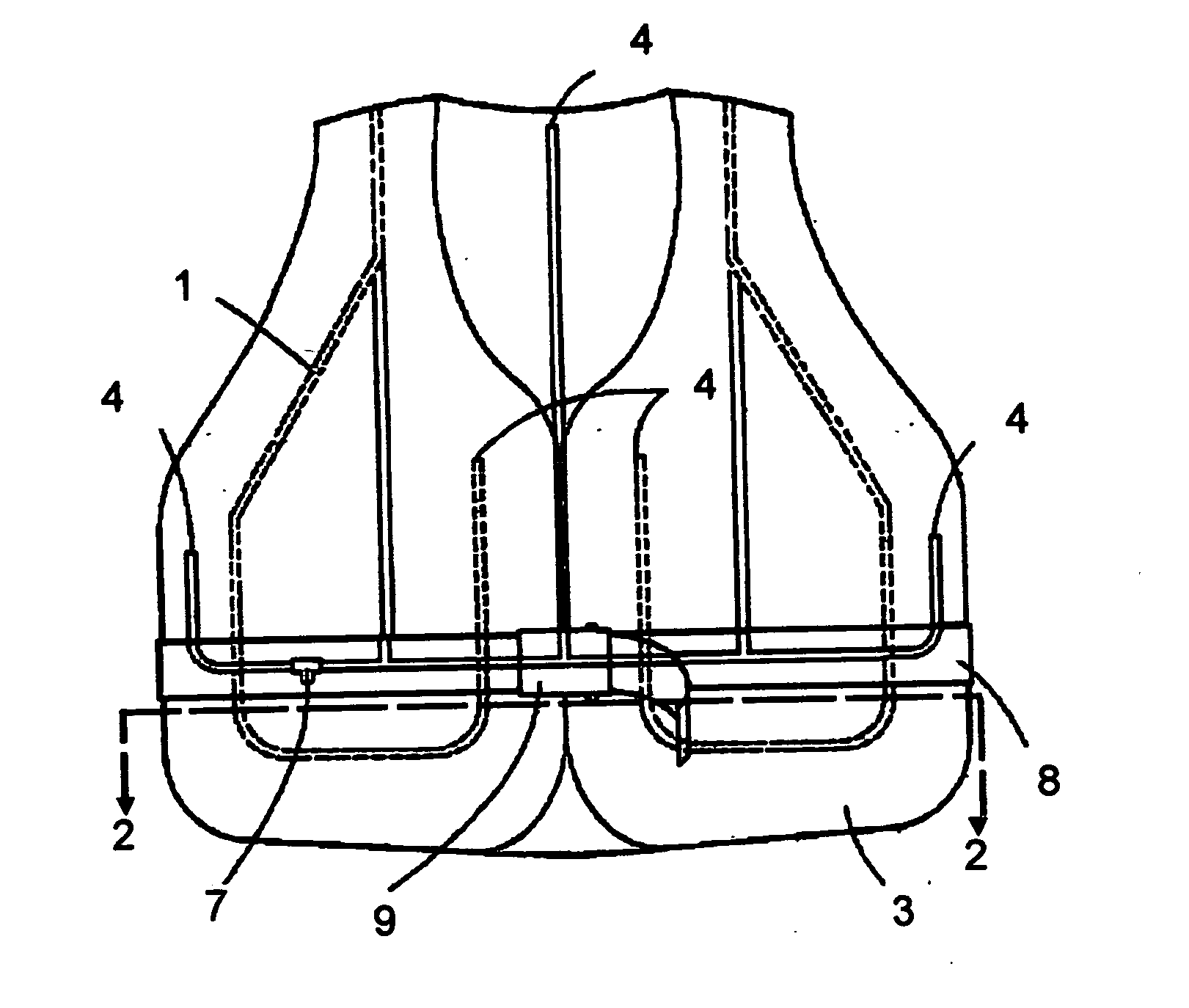
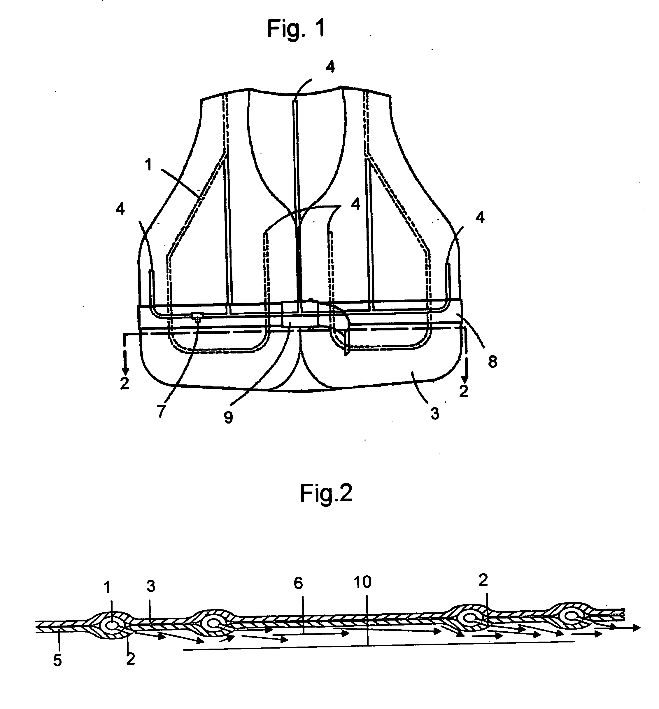
[0017] The preferred vest (FIG. 1) would be an air expansion vest with pressureized tubing 1 where the orientation of the pressurized tubing vent nozzles 2 (FIG. 2) or holes and a wind tight 3 covering would allow coanda enhanced evaporative cooling and cooling through the drop in air pressure and consequental drop in the temperature of the cooling air. The the pressurized tubes would be capped on the ends 4 (FIG. 1) to maintain back pressure in the tubing. These several significant improvements that in aggregate would significantly change the cooling method by utilizing the natural dryness of compressed air and its ability to phase shift and evaporate the moisture present on the surface of the body 10 (FIG. 2) and markedly increase the efficiency of this vest over others. First the holes 2 (FIG. 2) drilled in the tubes sewn into the vest would be aligned almost parallel to the surface of the body 10 (FIG. 2) rather than perpendicular. The outer shell would be comprised of a flam...


PUM


Abstract

The proposed invention is a method of cooling the human body using compressed air in the manner described by U.S. Pat. No. 5,438,707 without the necessity of directing the nozzles of the air jets directly at the body. The proposed invention directs the air jets in a parallel manner to the surface of the body thus cooling by both the expansion of the gas and evaporative cooling enhanced by larger contact with said surface of the body. Said air jets also cool by a coanda effect that entraps large amounts of air and pulls it along the surface of the body thus increasing evaporation. The present invention also entraps the cold air within a wind resistant cover replacing the mesh outer cover design.

Description

1. FIELD OF THE INVENTION [0001] The present invention relates to body garments capable of cooling the human body. These garments provide cooling of an individual by utilizing rapid depressurization of compressed gases adjacent the wearer as described in U.S. Pat. No. 5,438,707 issued to Stephen T. Horn on Aug. 8, 1995 but complements and enhances the cooling of the vest with evaporative cooling and eliminates a serious safety issue while using the coanda effect to further increase the evaporative cooling efficiency of the garment without increasing either the volume or pressure of the air used. 2. DESCRIPTION OF THE PRIOR ART [0002] Body garments for the purpose of cooling appear in the patent record taking many shapes and forms. However, the present invention is an air vest that uses the expansion of air as described by Charles law to cool the air where the air is now entrapped and diverted and the coanda effect is used to greatly enhance the evaporative cooling of the depressuriz...

Claims


Application Information

Patent Timeline
IPC IPC(8): A41D13/005
CPCA41D13/0053
Inventor HORN, STEPHEN T.
Owner HORN STEPHEN T
Learn More