Electrophotographic photoreceptor, and image forming method, image forming apparatus and process cartridge therefor using the electrophotographic photoreceptor
- Summary
- Abstract
- Description
- Claims
- Application Information
AI Technical Summary
Benefits of technology
Problems solved by technology
Method used
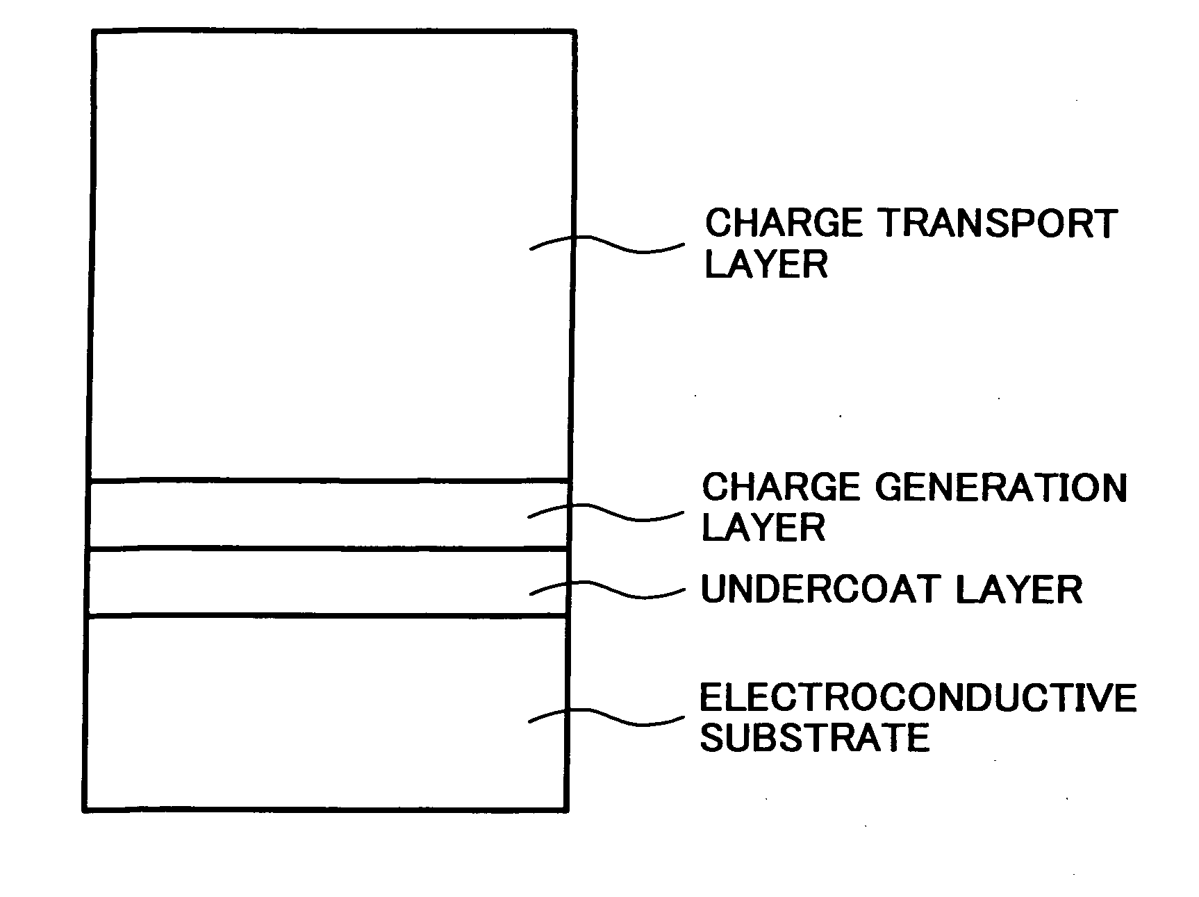
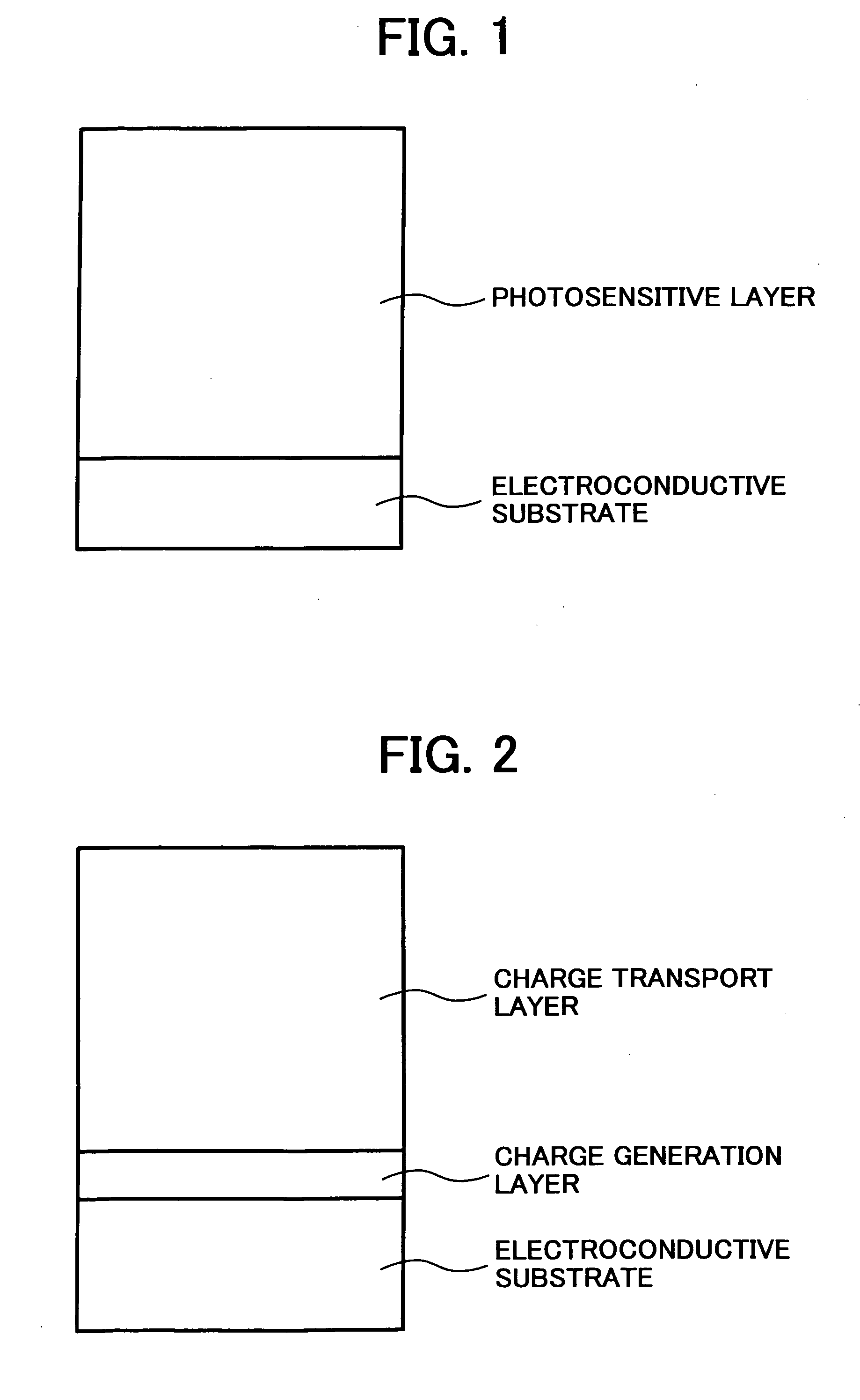
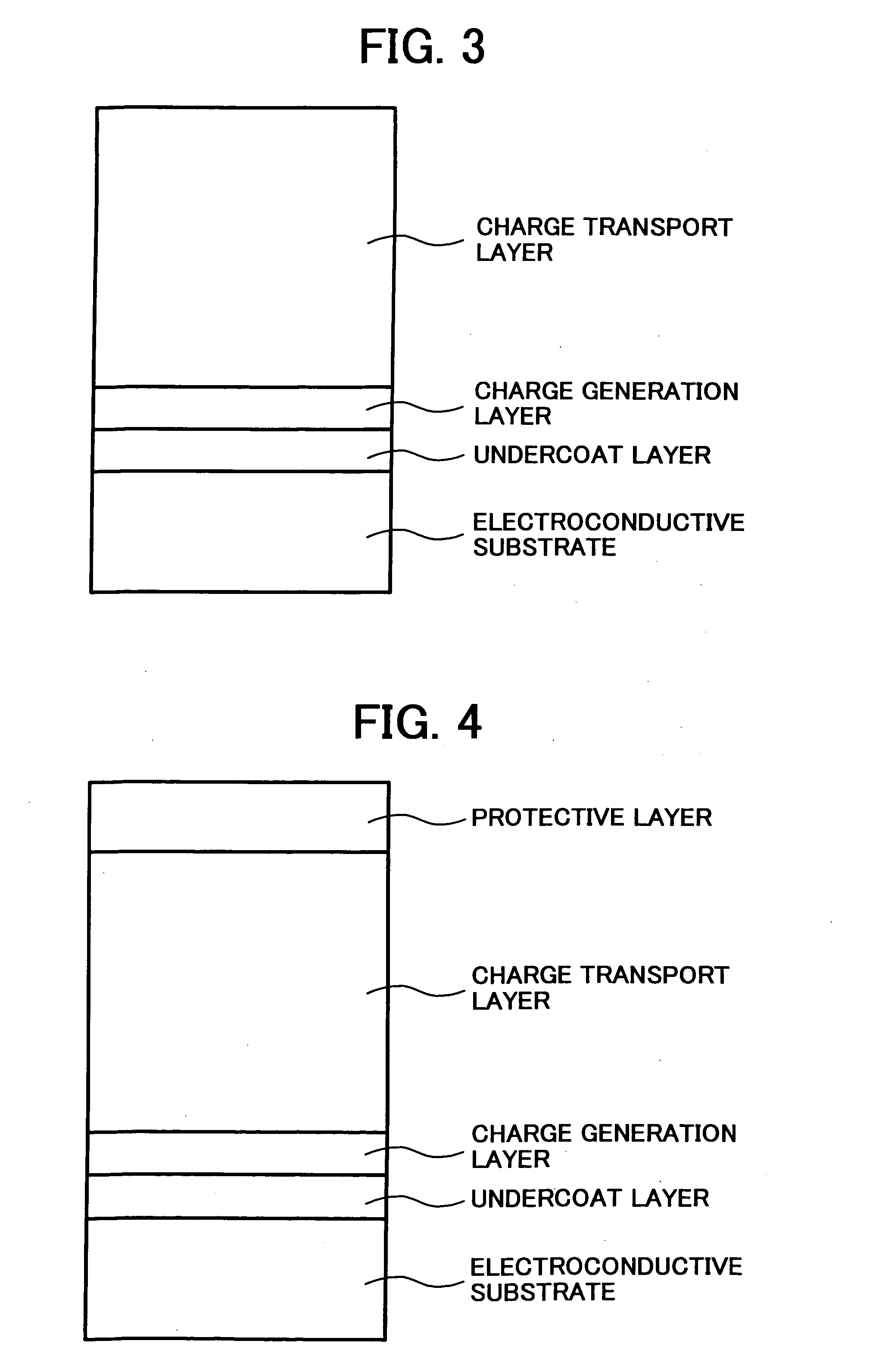
Image

Examples
example 1
[0168] The following materials were mixed and dispersed in a ball mill for 12 hrs to prepare an undercoat layer coating liquid:
Alkyd resin (Bekkolite M6401-50 from15Dainippon Ink & Chemicals, Inc.)Melamine resin (Super Bekkamin G-821-60 from10Dainippon Ink & Chemicals, Inc.)Methyl ethyl ketone150Titanium oxide powder (Tipaque CR-El from90Ishihara Sangyo Kaisha, Ltd.)
[0169] The thus prepared undercoat layer coating liquid was coated on a cylindrical aluminium substrate having a diameter of 90 mm and a length of 392 mm by a dip coating method, and the coated liquid was dried at 130° C. for 20 min to form an undercoat layer having a thickness of 3.5 μm on the substrate.
[0170] Next, the following materials were mixed and dispersed in a ball mill for 48 hrs to prepare a mixture:
Polyvinylbutyral resin 4(XYHL from Union Carbide Corp.)Cyclohexanone150Bisazo pigment having the following 10Formula (1):(1)
[0171] Further, 210 parts of cyclohexanone were included in the mixture and the mixt...
example 2
[0191] The procedures of preparation and evaluation of the electrophotographic photoreceptor in Example 1 were repeated to prepare and evaluate an electrophotographic photoreceptor of Example 2 except for including 55 parts of the PFA dispersion in the resin liquid formed of 16 parts of Bisphenol Z-type polycarbonate resin dissolved in the mixed solvent of 420 parts of tetrahydrofuran and 120 of cyclohexanone to prepare a coating liquid; and insonifying the coating liquid for 10 min to prepare a protective layer coating liquid.
example 3
[0192] The procedures of preparation and evaluation of the electrophotographic photoreceptor in Example 1 were repeated to prepare and evaluate an electrophotographic photoreceptor of Example 3 except for including 300 parts of the PFA dispersion in the resin liquid formed of 16 parts of Bisphenol Z-type polycarbonate resin dissolved in the mixed solvent of 420 parts of tetrahydrofuran and 120 of cyclohexanone to prepare a coating liquid; and insonifying the coating liquid for 10 min to prepare a protective layer coating liquid.
PUM
| Property | Measurement | Unit |
|---|---|---|
| Fraction | aaaaa | aaaaa |
| Fraction | aaaaa | aaaaa |
| Fraction | aaaaa | aaaaa |
Abstract
Description
Claims
Application Information
 - R&D
- Intellectual Property
- Life Sciences
- Materials
- Tech Scout
- Unparalleled Data Quality
- Higher Quality Content
- 60% Fewer Hallucinations
Browse by: Latest US Patents, China's latest patents, Technical Efficacy Thesaurus, Application Domain, Technology Topic, Popular Technical Reports.
© 2025 PatSnap. All rights reserved.Legal|Privacy policy|Modern Slavery Act Transparency Statement|Sitemap|About US| Contact US: help@patsnap.com