
Vehicle wheel speed estimation device, vehicle body speed estimation device and vehicle behavior control apparatus

a technology of vehicle behavior and estimation device, which is applied in the direction of vehicle components, braking systems, electric/fluid circuits, etc., can solve the problems of inadequate vehicle behavior stabilization effect and increase in vehicle wheel speed, so as to improve vehicle behavior control characteristics and improve accuracy

Inactive Publication Date: 2005-03-03
ADVICS CO LTD
View PDF9 Cites 12 Cited by
  • Summary
  • Abstract
  • Description
  • Claims
  • Application Information

AI Technical Summary

Benefits of technology

It is a further object of the invention to provide a vehicle body speed estimation device that can estimate a vehicle body speed based on a vehicle wheel speed of an inside wheel of a vehicle when high lateral acceleration is acting thereon, this inside wheel being located at an inside of a turning direction of the vehicle.
Moreover, it is a further object of the invention to provide a vehicle behavior control apparatus that can stabilize vehicle behavior based upon a vehicle wheel speed and a vehicle body speed that are estimated while high lateral acceleration is acting on a vehicle.
According to a first aspect of the invention, among a pair of left and right drive wheels, one of the drive wheels is taken to be a controlled wheel to which braking force is applied, and the other of the drive wheels is taken to be a non-controlled wheel to which braking force is not applied. A magnitude of a detected actual vehicle wheel speed of the non-controlled wheel is corrected to a smaller value based on the driving force applied to the controlled wheel. Note that, on some occasions, drive torque of the controlled wheel that is one of the drive wheels is partially transferred to the non-controlled wheel that is the other one of the drive wheels. Resultantly, the drive torque of the non-controlled wheel is increased, whereby the vehicle wheel speed of the non-controlled wheel is increased such that it become larger than the vehicle body speed at the position of the non-controlled wheel. However, according to the invention, it is possible to correct the vehicle wheel speed of the non-controlled wheel to a smaller value in accordance with the braking force applied to the controlled wheel. Accordingly, it is possible to correct the vehicle wheel speed of the non-controlled wheel to be closer to an actual vehicle body speed at the position of the non-controlled wheel. The vehicle wheel speed obtained by the invention may be utilized, for example in a braking control that performs vehicle behavior stability control or the like. Such braking controls are based upon vehicle body speed, and thus application of the invention makes it possible to improve brake control performance.
According to a second aspect of the invention, among a pair of left and right drive wheels, one of the drive wheels is taken to be a controlled wheel to which braking force is applied, and the other of the drive wheels is taken to be a non-controlled wheel to which braking force is not applied. A magnitude of a detected actual vehicle wheel speed of the non-controlled wheel is corrected to a smaller value based on a physical quantity that corresponds to a difference of a vertical load of the controlled wheel and a vertical load of the non-controlled wheel. Note that, on some occasions, drive torque of the controlled wheel that is the drive wheel with larger vertical load is partially transferred to the non-controlled wheel that is the drive wheel with smaller vertical load. Resultantly, the drive torque of the non-controlled wheel is increased, whereby the vehicle wheel speed of the non-controlled wheel with the smaller vertical load is increased such that it becomes larger than the vehicle body speed at a vehicle wheel position of the non-controlled wheel. However, according to the invention, the vehicle wheel speed of the non-controlled wheel is corrected to a smaller value in accordance with the vertical load of the controlled wheel. Accordingly, it is possible to correct the vehicle wheel speed of the non-controlled wheel to be closer to the actual vehicle body speed at the position of the non-controlled wheel. The vehicle wheel speed obtained by the invention may be utilized, for example in a braking control that performs vehicle behavior stability control or the like. Such braking controls are based upon vehicle body speed, and thus application of the invention makes it possible to improve brake control performance.
Moreover, the vehicle wheel speed of the non-controlled wheel that has been corrected in this way by the vehicle wheel speed estimation device may be used to estimate the vehicle body speed of the vehicle. By doing so, it is possible to improve the accuracy with which the vehicle body speed is estimated.
Further, a vehicle body speed estimation device according to the invention may be provided in a vehicle behavior control apparatus. In this case, control of vehicle behavior can be based on a vehicle body speed that is estimated by the vehicle body speed estimation device, whereby it is possible to improve the characteristics of the behavior control of the vehicle.

Problems solved by technology

However, in the related art, the fact that the vehicle wheel speed increases due to increase in the drive torque of the inside wheel when high lateral acceleration is acting is not taken into consideration.
When vehicle behavior control is perform based upon these inaccurate parameters, there are occasions when the resultant vehicle behavior stabilization effect is inadequate.

Method used


Image

  • Vehicle wheel speed estimation device, vehicle body speed estimation device and vehicle behavior control apparatus
  • Vehicle wheel speed estimation device, vehicle body speed estimation device and vehicle behavior control apparatus
  • Vehicle wheel speed estimation device, vehicle body speed estimation device and vehicle behavior control apparatus

Examples


Embodiment Construction

The present invention will be described further with reference to various embodiments in the drawings.

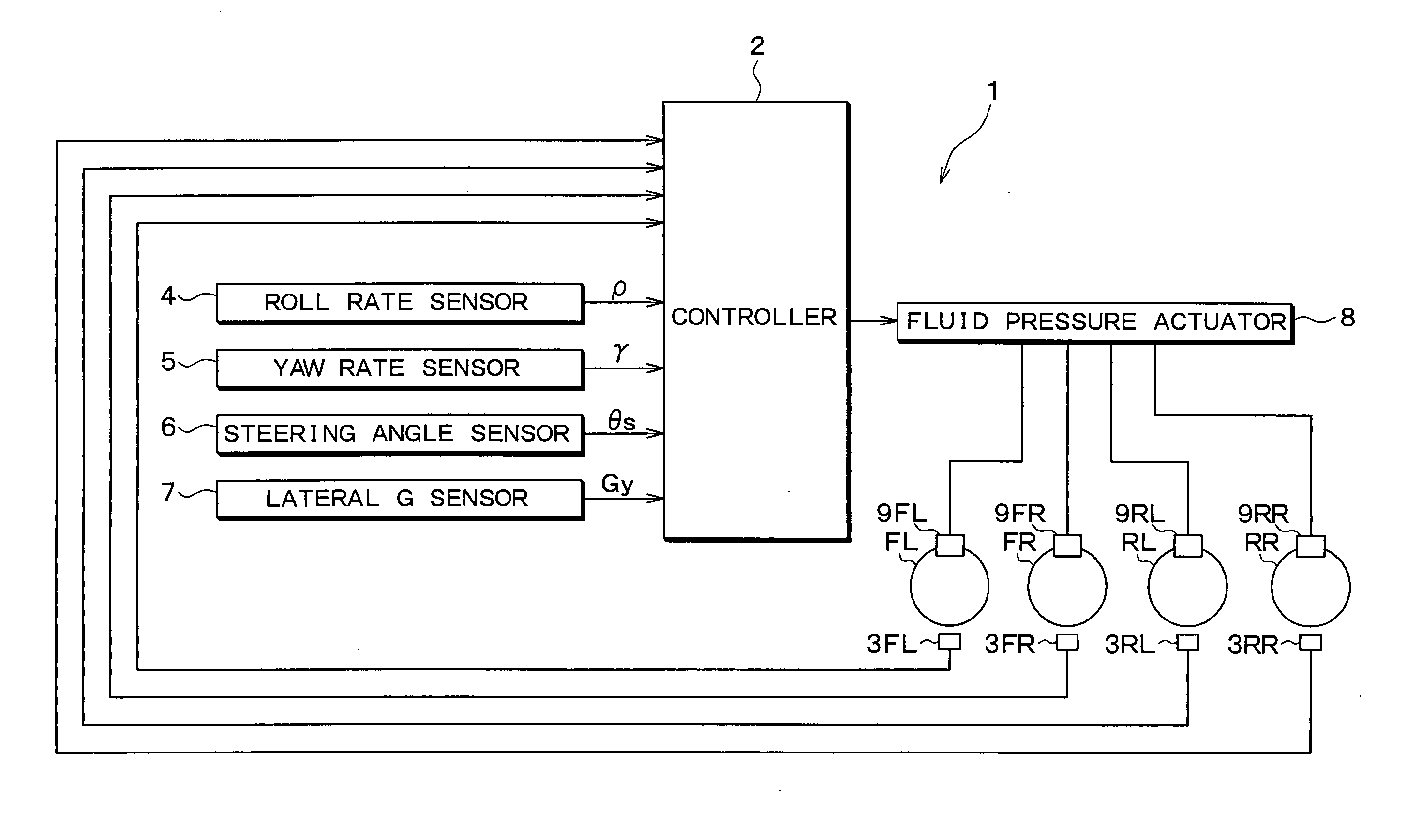
Hereinafter, an embodiment of the invention will be explained with reference to the drawings. FIG. 1 is a schematic representation of a vehicle behavior control apparatus 1 that acts as a braking force control apparatus that is provided with a vehicle wheel speed estimation device of an embodiment of the invention. This vehicle behavior control apparatus 1 can select, at the least, one of four vehicle wheels FL, FR, RL and RR, and perform control of a braking force of the selected vehicle wheel so as to stabilize vehicle behavior. Note that, more specifically, the front left wheel is denoted as FL, the front right wheel as FR, the rear left wheel as RL, and the rear right wheel as RR.

The vehicle behavior control apparatus 1 of the embodiment includes a controller 2 that is configured from a microcomputer.

The vehicle behavior control apparatus 1 includes vehicle wheel sensors ...


PUM


Abstract

In a case where one of a left and right pair of drive wheels is a non-controlled wheel to which braking force of a vehicle behavior control is not applied, and the other of the drive wheels is a controlled wheel to which braking force is applied, a detected vehicle wheel speed for the non-controlled wheel is corrected to a smaller value in accordance with increase in the roll angle, and increase in the braking force of the controlled wheel when a roll angle of a vehicle body is larger than a threshold value. In a vehicle behavior control, when lateral G acts upon the vehicle during turning, braking force is applied to the controlled wheel that is at the outside of the turn. This braking force application causes driving force of the controlled wheel to be partially transferred to the non-corrected wheel that is at the inside of the turn, whereby the vehicle wheel speed of the non-corrected wheel is increased. Accordingly, in the present invention, correction calculation is performed.

Description

CROSS REFERENCE TO RELATED APPLICATION This application is based upon and claims the benefit of Japanese patent application No. 2003-301419 filed on Aug. 26, 2002, the content of which are incorporated herein by reference. FIELD OF THE INVENTION The present invention relates to a vehicle wheel speed estimation device for estimating a wheel speed of a vehicle, a vehicle body speed, estimation device for estimating vehicle body speed and a vehicle behavior control apparatus for stabilizing vehicle behavior. BACKGROUND OF THE INVENTION A free rotational speed estimation device is known (for example, Japanese Patent No. 3412363) that calculates a vehicle body speed and respective free rotational speeds of vehicle wheels of a vehicle (“free rotational speed” as used here refers to the rotational speed of each vehicle wheel when no braking force is applied). The calculated results of this free rotational speed estimation device are utilized in a vehicle behavior control apparatus that ...

Claims


Application Information

Patent Timeline
IPC IPC(8): B60R16/02B60T8/172B60T8/1755B60T8/24B60T8/58B60T8/60B60T8/66
CPCB60T2250/04B60T8/172
Inventor BANNO, MASAKIMATSUOKA, HIROSHITAGAWA, SHINICHI
Owner ADVICS CO LTD
Learn More