
Device for selectively detecting specific wavelength components of a light beam

a technology of specific wavelength components and light beams, applied in the direction of optical radiation measurement, fluorescence/phosphorescence, instruments, etc., can solve the problems of inflexible design, inability to change the composition of the spectral regions to be detected, and the system is extremely complex. , to achieve the effect of simple and flexible design

Inactive Publication Date: 2005-03-03
LEICA MICROSYSTEMS CMS GMBH
View PDF2 Cites 6 Cited by
  • Summary
  • Abstract
  • Description
  • Claims
  • Application Information

AI Technical Summary

Benefits of technology

[0005] It is therefore an object of the present invention to provide a device for selectively detecting specific wavelength components of a light beam and a method for suppressing excitation lines in the detection light beam of a microscope in such a manner that the detection of unwanted wavelength components of a light beam to be detected is suppressed to a large extent using a simple and flexible design.
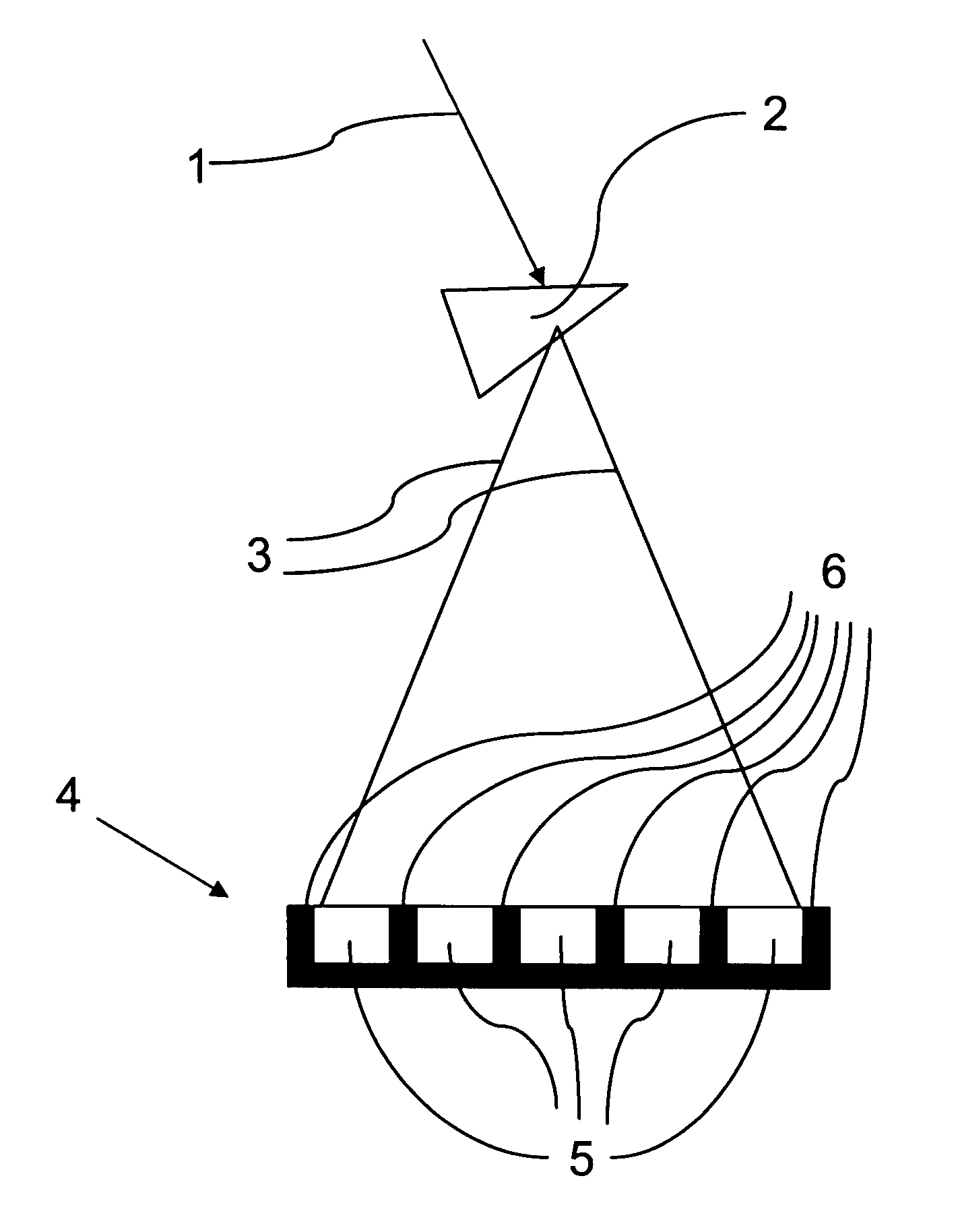
[0007] In accordance with the present invention, it was discovered that in order to avoid detection of unwanted wavelength components of a light beam, it is not absolutely necessary to block the wavelength components from the optical path of the light beam in a complex manner before they reach the detector. Rather, in accordance with the present invention, the element for spectrally spreading out the light beam and the detector in the form of a detector array are matched to each other in such a manner that the unwanted wavelength components hit light-insensitive regions of the detector array. Thus, the present invention takes advantage of the special design of the detector array, which, for manufacturing and functional reasons, has light-insensitive regions between the actual photosensitive regions, i.e., the so-called channels. When these photo-inactive regions are adjusted to coincide with the unwanted wavelength components, these components may thus be easily suppressed during detection.
[0010] To increase the variability of the device, provision could be made that the detector array, the mask and / or the micro-optical element be movable independently of each other. In this connection, it is advantageous for the fine adjustment of the individual components if the individual components are movable in three translational and three rotational degrees of freedom.
[0011] A specific possible use of the device is, in particular, the use in a fluorescence microscope. In a fluorescence microscope, an excitation light beam of an illumination light source is directed via microscope optics onto a sample from which a detection light beam emanates. In this connection, the excitation light reflected by the sample and contained in the detection light beam could, at least partially, hit light-insensitive regions of the detector array while the fluorescent light produced in the sample hits light-sensitive regions. This allows excitation lines to be excluded from detection in a particularly sophisticated manner.
[0013] In accordance with the present invention, it was discovered that detection of the excitation lines can be avoided by matching the element for spectrally spreading out the detection light beam and the detector array to each other in such a manner that the excitation lines hit light-insensitive regions of the detector array. Thus, the detector array “sees” a reduced light intensity, i.e., essentially only the actual detection light, in particular, fluorescent light, and the number of occurrences of electronic crosstalk between the channels is markedly reduced.

Problems solved by technology

Having a multitude of components, this system is extremely complex and in addition not very flexible in terms of a changed composition of the spectral regions to be detected.
In this connection, it is a disadvantage that the absorption is generally not complete so that in spite of the filtering, there is still excitation light hitting the detector.
This is problematic especially when the intensity of the excitation line is many times greater than the intensity of the actual detection light, which is typically the case in fluorescence microscopy.
A further disadvantage is that the filtering generally also affects the detection light, thus corrupting the measurement result.

Method used


Image

  • Device for selectively detecting specific wavelength components of a light beam
  • Device for selectively detecting specific wavelength components of a light beam
  • Device for selectively detecting specific wavelength components of a light beam

Examples


Embodiment Construction

[0025]FIG. 1 schematically shows an exemplary embodiment of a device for selectively detecting specific wavelength components of a light beam 1. For spectral spreading, light beam 1 initially passes through a prism 2, and then the spread-out light beam 3 hits a detector array 4. Detector array 4 is a commercial CCD line detector or a commercial PMT array, which have “photo-inactive” regions 6 (shown dark in FIG. 1) between the individual photosensitive regions 5 (channels) shown bright. These regions 6, which are insensitive to light, are basically attributable to the manufacturing process and the design of detector array 4, but may also be artificially created at a later time.

[0026] In accordance with the present invention, prism 2 and detector array 4 are matched to each other in such a manner that the wavelength components of light beam 1, 3 that are not to be detected hit insensitive regions 6 of detector array 4 while the remaining wavelength components of light beam 1, 3, whi...


PUM

PropertyMeasurementUnit
degrees of freedomaaaaaaaaaa
specific wavelengthaaaaaaaaaa
wavelengthaaaaaaaaaa

Abstract

A device for selectively detecting specific wavelength components of a light beam includes a spectral spreading element for spectrally spreading the light beam, and a detector array arranged downstream of the element. The detector array includes light-insensitive regions and light-sensitive regions. The element and the detector array are matched to each other so that selectable wavelength components of the light beam hit the light-insensitive regions and remaining wavelength components of the light beam hit the light-sensitive regions.

Description

[0001] Priority is claimed to provisional application 60 / 563,117, filed Apr. 16, 2004, and to German patent application 103 40 020.6, filed Aug. 28, 2003, the entire disclosure of each of which is hereby incorporated by reference herein.[0002] The present invention relates to a device for selectively detecting specific wavelength components of a light beam, including an element for spectrally spreading out the light beam and a detector array downstream of the element. The present invention further relates to a method for suppressing excitation lines in the detection light beam of a microscope, in particular for use in a fluorescence microscope, in which an element for spectrally spreading out the detection light beam and a detector array downstream of the element are disposed in the optical path of the detection light beam. BACKGROUND [0003] Devices for selectively detecting specific wavelength components of a light beam have been used in practice for quite some time, reference bein...

Claims


Application Information

Patent Timeline
Patent Type & Authority Applications(United States)
IPC IPC(8): G01J3/14G01J3/28G01J3/36G01J3/44G01N21/64
CPCG01J3/0229G01J3/14G01N21/6458G01J3/36G01J3/4406G01J3/2803
Inventor BIRK, HOLGERSEYFRIED, VOLKERSTORZ, RAFAEL
Owner LEICA MICROSYSTEMS CMS GMBH
Learn More