
In-wheel electric motors

a technology of electric motors and electric motors, applied in the direction of electric propulsion mounting, magnetic circuit shape/form/construction, electric devices, etc., can solve the problems of increased unsprung mass, negative effect on motor performance, and consequent effect on ride and handling

Inactive Publication Date: 2005-03-03
BLUWAV SYST LLC
View PDF87 Cites 98 Cited by
  • Summary
  • Abstract
  • Description
  • Claims
  • Application Information

AI Technical Summary

Benefits of technology

[0013] The natural rotary motion of an electric motor matches nicely with the natural rotary motion of a wheel. That gives a simple elegance to fitting an electric motor directly into the wheel of a vehicle. This is not a new idea—Ferdinand Porsche designed electric cars in 1900 and 1902 using in-wheel electric motors.
[0014] Many car designers continue to believe that in-wheel, or “hub,” motors provide the best architecture for electric cars. Some of the main advantages of in-wheel motors are higher efficiency, better traction control, weight and space savings, and quiet operation.
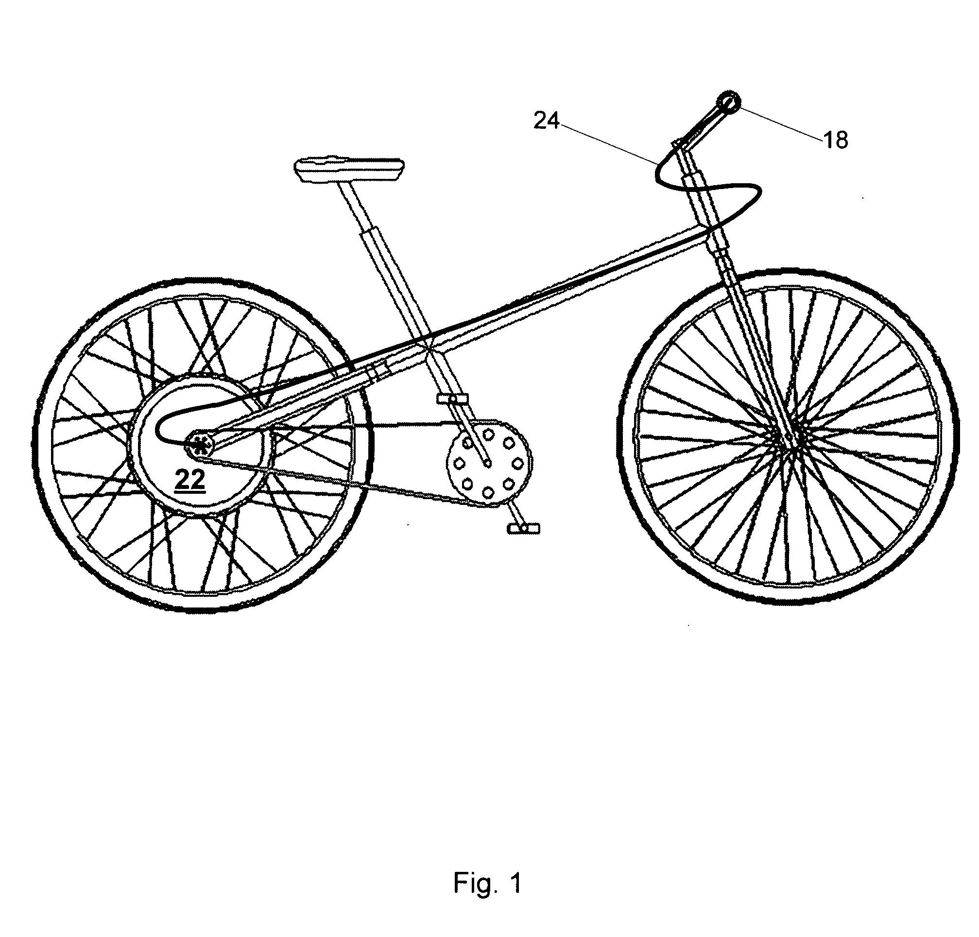
[0015] Direct-drive wheel systems in cars consist of a motor drive coupled directly to a driven wheel without any intervening transmission or differential. This arrangement simplifies the drive train considerably. In bicycles, in-wheel motors eliminate the need for any efficiency-robbing mechanism that uses friction to rotate the wheels.
[0016] With today's cars, engines create rotating power, or torque. That energy is transferred to a set of gears, or a transmission. The gears turn a drive shaft and ultimately spin the wheels. Typically, at least Ten percent of the power created by the engine is lost transferring energy to the wheels.
[0017] The ability of an in-wheel motor to start from zero speed makes it possible to eliminate the need for a clutch in cars. The available speed range usually makes transmission gears unnecessary. Planetary gears allow the motor to run at much higher speed for a given road speed, this usually produces a much higher torque at the motor's peak torque range. Using them may add considerably to the efficiency of the complete power train for some applications.
[0018] As much as three percent of the power created by the engine in a normal car may be lost to brake drag. Because the in wheel motor has a very fast response the brake drag can be eliminated by using high roll back calipers. In addition, with an in-wheel motor, regenerative braking can possibly recover 50 to 70% of the vehicle's kinetic energy . Road conditions and compromises in stability may reduce this number to 20-30%

Problems solved by technology

Some problems of in-wheel motors in cars include the possible increase in unsprung mass and the consequent effect on ride and handling; in addition, the effect of heat from braking negatively effects motor performance.
Packaging motors in the wheel adds an additional vulnerability to environmental conditions resulting in potential damage of a motor in this exposed position.
Typically, at least Ten percent of the power created by the engine is lost transferring energy to the wheels.
The available speed range usually makes transmission gears unnecessary.
As much as three percent of the power created by the engine in a normal car may be lost to brake drag.
Putting an electric motor in or near the wheel in a car saves a lot of weight and space.
Eliminating those devices saves weight and space.
This need for a distributed control system may seem like a drawback.
But conventional four-wheel drive systems also require a relatively complex control system to regulate the performance of the drive train.
In addition, a modern conventional four wheel drive train and transmission system is quite complex mechanically and very expensive to manufacture.
Fifth, motor torque becomes easily comprehensible.
With a transmission, differential and other drive line components between a gasoline engine and a car's wheels, the actual torque exerted on the wheel may be hard to determine.
Brakes also make actual applied torque hard to determine.
Existing motor technology cannot easily meet the high performance demands required of in-wheel motors.
Several problems arise.
Putting a heavy motor in a wheel of a car increases its unsprung mass.
That can have dramatic, negative effects on the car's comfort, handling and road-holding performance.
Most electric motors and all internal combustion engines are too heavy to be removed from the body of a car and put into one or more of the drive wheels.
Too much weight in a car's wheels will have several effects on suspension and ride.
This causes excessive movement in the suspension, which produces a poor ride and reduces cornering grip.
In addition, higher unsprung mass requires stiffer shock absorbers to control the extra spring movement, which also contributes to a stiff, harsh ride.
This problem may not seem great.
But the effects are substantial and difficult to overcome.
The most stubborn drawback of in-wheel drive motors has been the weight that they add to each wheel.
That, more than any other reason, has limited the adoption of in-wheel motor systems in electric vehicles.
Some, like GM with its AUTOnomy concept car, have given up on in-wheel motors for cars, fearing that they will always be too heavy.
Problems from Location in the Wheel
Friction braking may create heat that affects motor performance.
Electrical cables leading to the wheels may need to be heavy (to carry large currents), long and unless protected, liable to be damaged.
The motor itself also becomes vulnerable to wet, heat and damage in a collision when put in a car's wheels.
Putting a powerful motor in the small space available in a vehicle's wheel may cause problems.
For example, there may be little room left for a cooling or lubrication system.
And the limitations of space and unsprung mass may limit the power of motor that may be used.
Trying to increase power without increasing weight by using planetary gears will bump into the space constraints as well.
Outside of this range, they quickly lose efficiency.
The obvious disadvantage is the need for two complete, separate electric motors.
With an in-wheel motor system, finding one type of motor that provides peak performance at low speeds and high speeds, and in other varying conditions, is difficult.
And using more than one type of motor in an in-wheel system seems impractical.
Not having a range of gears available will make it difficult to get enough torque at all speeds.
For example, pedaling a tricycle up a steep hill is impossible.
A human cannot generate enough torque to do that.
If it had only one gear, it would be practically useless.
But almost any suitable motor will be too big, heavy and expensive.
But existing motors typically do not have sufficient torque density to be a practical in-wheel motor.
In addition, an electric motor usually needs to operate at high voltage and high current to generate enough torque and power.
High current means a bulky, heavy, expensive motor and thick power cables.
High voltage means a safety issue for both car passengers and repair personnel.
High Cost and Complexity
A considerable amount of work has been done to develop motors suitable for in-wheel use, but it is a formidable task.
This is mainly because of the cost and complexity of producing the very small, high-torque, high-power motors required.
They are ill-suited for in-wheel motors.
A high-performance motor of this type uses expensive permanent magnets and requires a complicated control system.
That adds to the cost and complexity of an in-wheel motor of this type.
While these motors may work well in expensive prototypes and concept cars, they may not translate to practical production cars.

Method used


Image

  • In-wheel electric motors
  • In-wheel electric motors
  • In-wheel electric motors

Examples


Embodiment Construction

Advantages of In-Wheel Adaptive Motors

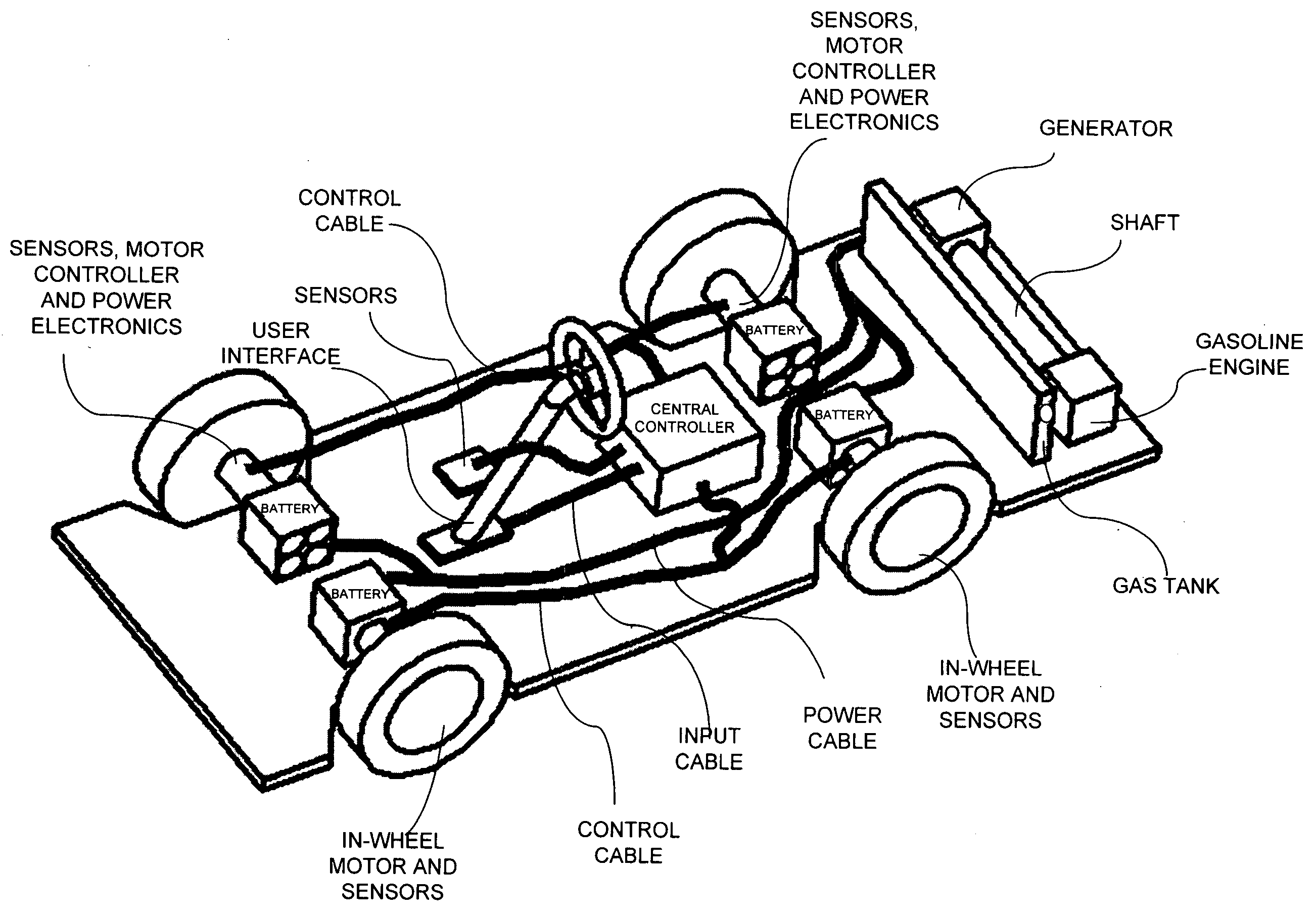
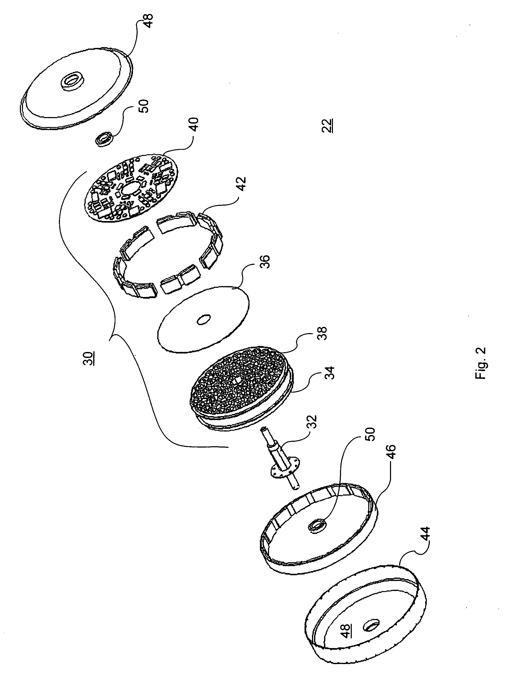
[0064] In-wheel adaptive motors solve or reduce many of the problems with existing in-wheel motor systems. In-wheel motors take up less space, have lower weight than conventional motors, provide more power than existing electric motors, are more efficient than prior art electric motors, and provide greater reliability and performance than existing electric motors while being more economical to produce.

[0065] There are various features of the electric motors of the present invention that provide for the above-mentioned advantages over prior art design. These features include segmented magnetic circuits enabling premier torque production, fast response and precise control of motor output, and soft magnetic electromagnets and shaped pole heads which enable unprecedented torque density. Further, independent pole control and phase advance enables greater than average efficiency for an electric motor.

[0066] The adaptive control systems of these mot...


PUM


Abstract

Improved in-wheel, near-wheel and direct-drive electric motors for cars and other vehicles. This motor can be cheaper, lighter, more powerful, more efficient, and more reliable than other direct-drive motors. Its high torque-density and high performance allow it to produce the same peak power as heavier, bigger motors. That helps greatly with the handling issues caused by too much unsprung mass. The motor control system can adapt to the vehicle's operating conditions (like starting, accelerating, turning, braking, and cruising at high speeds). That provides better performance. The motor's low-voltage, low-current design helps reduce heat and weight and leads to lower motor cost. The motor can still operate with some faults, offering “get home” capability. It offers all the benefits of in-wheel motors: efficiency, compactness, direct traction control, quiet, simple driveline. And it adds to those benefits, while reducing or eliminating the drawbacks other in-wheel motors.

Description

STATEMENT OF RELATED APPLICATION [0001] This application is a continuation-in-part of U.S. application Ser. No. 10 / 359,305 filed Feb. 6, 2003, which application claims priority from commonly assigned, copending U.S. application Ser. No. 09 / 826,423 of Maslov et al., filed Apr. 5, 2001, commonly assigned, copending U.S. application Ser. No. 09 / 826,422 of Maslov et al., filed Apr. 5, 2001, commonly assigned, copending U.S. application Ser. No. 09 / 966,102, of Maslov et al., filed Oct. 1, 2001, commonly assigned, copending U.S. application Ser. No. 09 / 993,596 of Pyntikov et al., filed Nov. 27, 2001, commonly assigned, copending U.S. application Ser. No. 10 / 173,610, of Maslov et al., filed Jun. 19, 2002, commonly assigned, U.S. application Ser. No. 60 / 399,415, of Maslov et al., filed Jul. 31, 2002, commonly assigned, copending U.S. application Ser. No. 10 / 290,537, of Maslov et al., filed Nov. 8, 2002, commonly assigned, copending U.S. application Ser. No. 10 / 353,075 of Maslov et al., file...

Claims


Application Information

Patent Timeline
Patent Type & Authority Applications(United States)
IPC IPC(8): B60L8/00H02K1/14H02K1/18H02K3/28H02K11/00H02K11/04H02K16/04H02K29/00H02P6/00H02P23/00H02P25/08
CPCB60L8/00Y02T10/648B60L2220/18B60L2220/44H02K1/141H02K1/187H02K3/28H02K7/183H02K11/0073H02K11/044H02K11/046H02K16/04H02K21/22H02K29/00H02K2213/09H02P6/001H02P23/0077H02P25/08Y02T10/641Y02T10/646Y02T10/7083Y02T10/725B60L2210/20H02K11/33H02P6/34Y02T10/64Y02T10/7072Y02T10/72B60K1/00
Inventor MASLOV, BORIS A.PYNTIKOV, ALEXANDERPAVLOV, KEVIN
Owner BLUWAV SYST LLC
Learn More