
Pulley bearing for engine auxiliares

a technology of pulley and auxiliaire, which is applied in the direction of magnetically actuated clutches, mechanical equipment, hoisting equipment, etc., can solve the problems of short life, gradual damage of outer ring and the surface of the ball, and large difference in linear expansion coefficient between materials

Inactive Publication Date: 2005-02-24
NSK LTD
View PDF8 Cites 10 Cited by
  • Summary
  • Abstract
  • Description
  • Claims
  • Application Information

AI Technical Summary

Benefits of technology

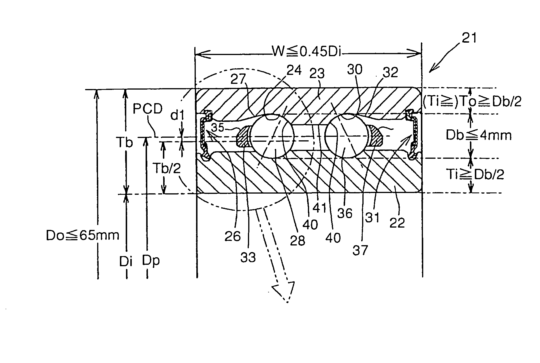
The present invention relates to a bearing for pulleys of engine auxiliaries. The technical effects of the invention include solving the problem of thermal expansion mismatch between the bearing material and the member to which the bearing is fixed, and ensuring the bearing's durability and stability under high-load conditions. Additionally, the invention addresses the problem of wear and corrosion caused by the use of certain materials and arrangements. The bearing design includes a pair of bearing rings with balls and a retainer, and a seal sealing the interior of the bearing. The width and thickness dimensions of the bearing are optimized, and the pitch diameter of the balls is close to the outer diameter of the bearing. The bearing material is EP steel with low oxygen content, and the outer and inner sides of the outer and inner raceway grooves are positioned close to the central axis of the bearing for better performance. The retainer is designed to minimize wear and corrosion, and a seal with multiple lips is used for better sealing.

Problems solved by technology

Moreover, the driven pulley is sometimes made of resin in recent years.
On the contrary, since the bearing is subject to great load developed when the compressor is driven and must rotatably bear the compressor in a stable manner over an extended period of time, it must be made of a bearing steel having a high strength and have its races properly surface-treated.
In particular, while most light alloys such as aluminum alloy have a great linear expansion coefficient, the bearing steel has a relatively small linear expansion coefficient, and since the recent rise of the internal temperature of engine room and the temperature during bearing operation cause the rise of the ambient temperature of the bearing and hence the expansion of the range of the working temperature of the bearing, the difference in linear expansion coefficient between the two materials has given a great problem.
When the running clearance is negative as mentioned above, the races on the inner ring and the outer ring and the surface of the balls gradually undergo damage and short life due to fatigue and temperature rise accompanying prolonged operation and this is extremely undesirable.
When the looseness of fitting of the shaft with the bearing is raised to cope with this problem, relative slippage occurs between the inner ring and the supporting axis to disable proper bearing action and generate noise at low temperature because the connecting force of the two parts is small.
In this case, however, a great clearance occurs in the bearing during low temperature operation, causing the general formula of great noise, and this is undesirable.
Accordingly, when the expansion of the driven pulley becomes great particularly during high temperature operation, the interference of the outer ring which has been initially assembled to the driven pulley with a predetermined interference is gradually lost, causing slippage relative to each other.
However, when such a great interference is predetermined, a great external force is acted on the outer ring to deform the outer ring, and in a bearing which has been predetermined to a certain initial clearance, the outer ring is provided with a clearance decreased by the inward deformation, occasionally making the initial clearance negative and hence causing trouble during low temperature operation to disadvantage.
Further, since the linear expansion coefficient of the material is great, an extreme negative clearance occurs at an extremely low temperature, causing problems such as excess torque and dent on the bearing race.
Moreover, the rise of the initial clearance for the purpose of preventing this problem causes the rise of clearance at high temperature resulting in the generation of noise.
This trouble is not limited to bearing for automobile compressor pulley but can apply to pulley bearings for other various engine auxiliaries.

Method used


Image

  • Pulley bearing for engine auxiliares
  • Pulley bearing for engine auxiliares
  • Pulley bearing for engine auxiliares

Examples


Embodiment Construction

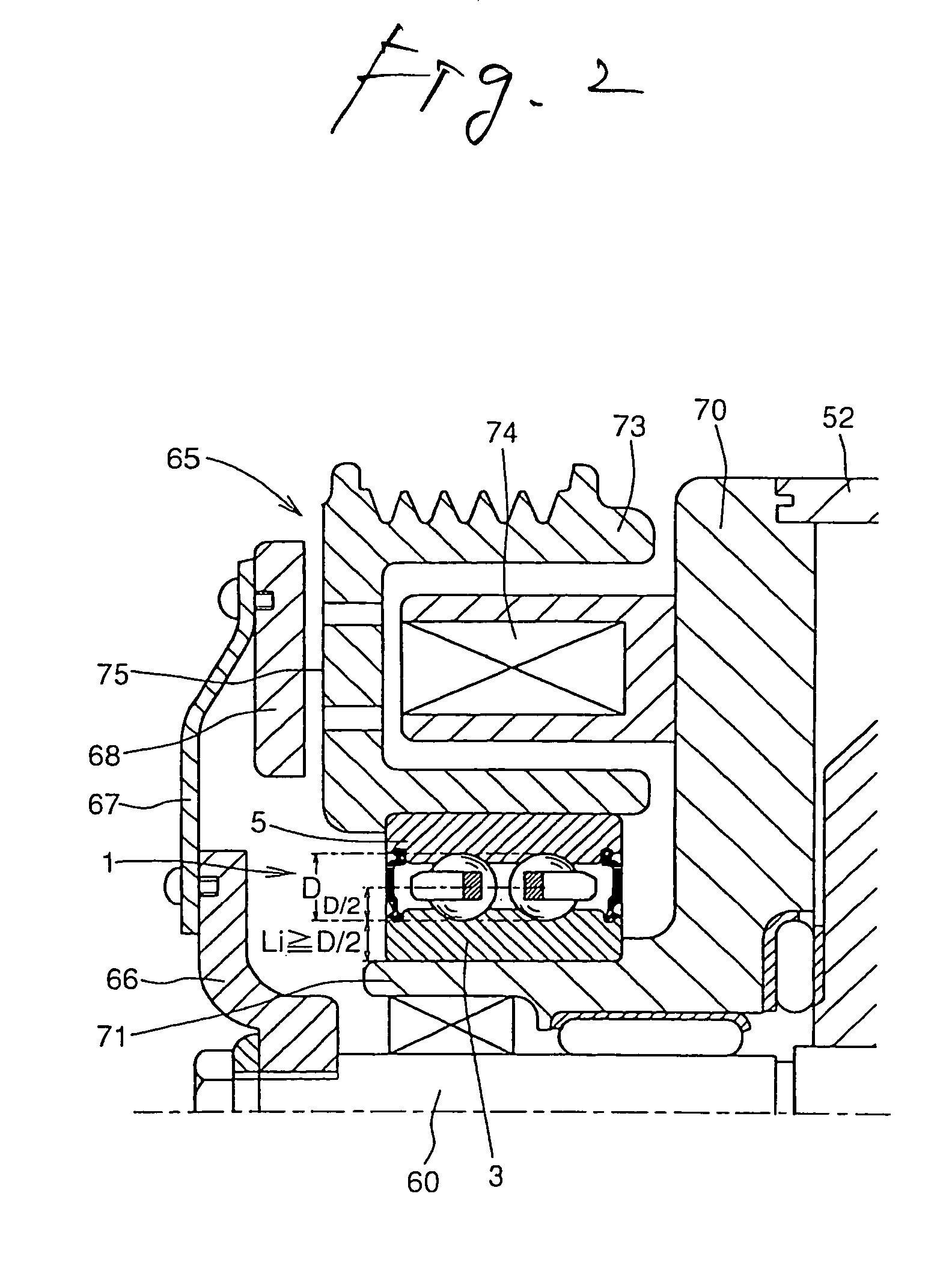
[0029] Embodiments of implementation of the present invention will be described in connection with the drawings and with reference to the results of experiments. There are various kinds of air conditioner compressors as automobile auxiliaries, and a compressor 51 as shown in FIG. 6 above is used for example, wherein a driven pulley 73 which drives a rotary shaft 60 is born by a bearing 72 at a bearing portion 71 protruding from an end casing 70. An enlarged view of a part including the driven pulley 73 and the bearing portion bearing the driven pulley 73 is shown in FIG. 2.

[0030]FIG. 2 shows an example of the application of a bearing comprising thicker inner ring and outer ring according to the present invention to a double-row bearing instead of a related art bearing 72 shown in FIG. 6 as described later. Accordingly, most of the members shown in FIG. 2 are the same as those shown in FIG. 6 and the various members, the operation of electromagnetic clutch, etc. were described in th...


PUM


Abstract

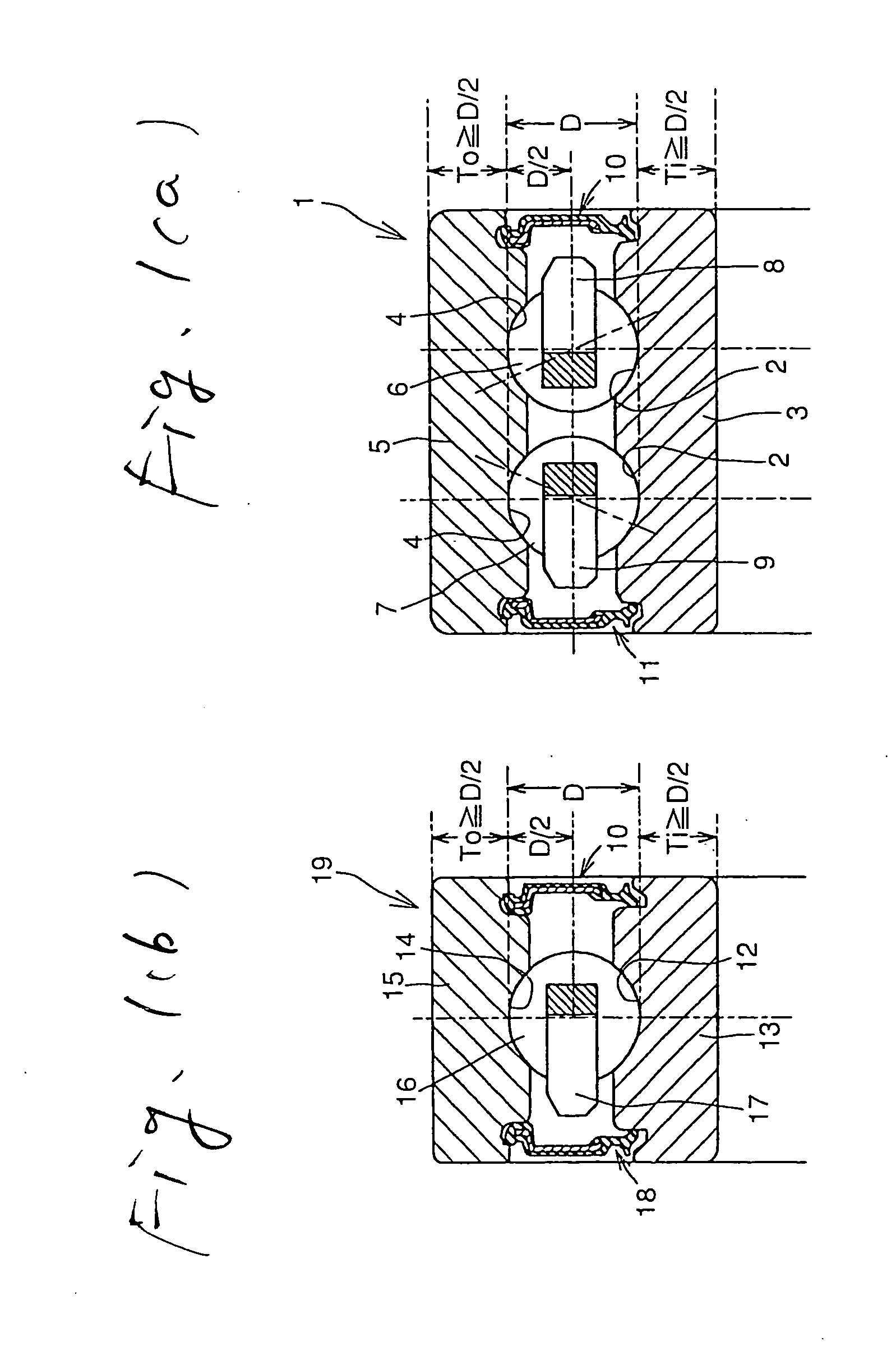
In the bearing of the present invention, the thickness of the bottom of at least one of the inner ring and the outer ring is 50% or more of the diameter of said balls. Further, the bearing comprises an outer ring having an outer diameter of 65 mm or less and balls having a diameter of 4 mm or less and has a width dimension of 45% or less of the inner diameter dimension thereof wherein the pitch diameter of the balls is closer to the outer side of the bearing than to the center of the section of the bearing, EP steel is used, the outer side of the outer raceway grooves is tapered, the inner side of angularly arranged outer raceway grooves is positioned closer to the central axis of the bearing than to the outer side of the outer raceway grooves, beveling or the like of the outer back side of the retainer is greater than half the section width or a seal having a plurality of lips fitted in an inner ring seal groove is provided.

Description

TECHNICAL FIELD [0001] The present invention relates to a bearing for bearing a pulley provided in an engine auxiliary such as automobile air conditioner compressor during the driving of the engine auxiliary by an engine via an endless belt and more particularly to a bearing for pulley of engine auxiliary capable of preventing adverse effects caused by the change of clearance in the bearing generated by the thermal expansion of fixed members of bearing, etc. BACKGROUND ART [0002] An automobile has various auxiliaries driven by an engine, and one of these auxiliaries is an air conditioner compressor and an endless belt extends between a driven pulley provided on the end of the rotary shaft of the compressor and a driving pulley of the engine so that the compressor is operated. An example of such a compressor is shown in FIG. 4. [0003] In a compressor 51 for vehicle compressor shown in FIG. 6, a piston 54 is disposed in a plurality of cylinders 53 formed in a casing 52 in such an arra...

Claims


Application Information

Patent Timeline
Patent Type & Authority Applications(United States)
IPC IPC(8): F16C19/06F16C19/16F16C19/18F16C33/41F16C33/58F16D27/112F16H55/36
CPCF16C19/06F16C19/163F16C19/184Y10S384/905F16C33/58F16H55/36F16C2361/63F16C33/414F16C2240/40F16C2240/60F16C19/08F16C19/18
Inventor OHATA, TOSHIHISAISHIGURO, HIROSHI
Owner NSK LTD
Learn More