
High speed low power magnetic devices based on current induced spin-momentum transfer

Active Publication Date: 2005-02-24
NEW YORK UNIVERSITY
View PDF17 Cites 53 Cited by
  • Summary
  • Abstract
  • Description
  • Claims
  • Application Information

AI Technical Summary

Benefits of technology

[0008] In view of the limitations associated with conventional designs of devices that use spin-momentum transfer, an object of the present invention is to provide a structure that is optimal for a magnetic memory or magnetic information processing device.
[0009] It is another object of the present invention to produce a magnetic device that has advantages in terms of speed of operation.
[0010] It is a further object of the present invention to produce a magnetic device that has advantages in terms of reliability.
[0011] It is a further object of the present invention to produce a magnetic device that requires lower power to operate.
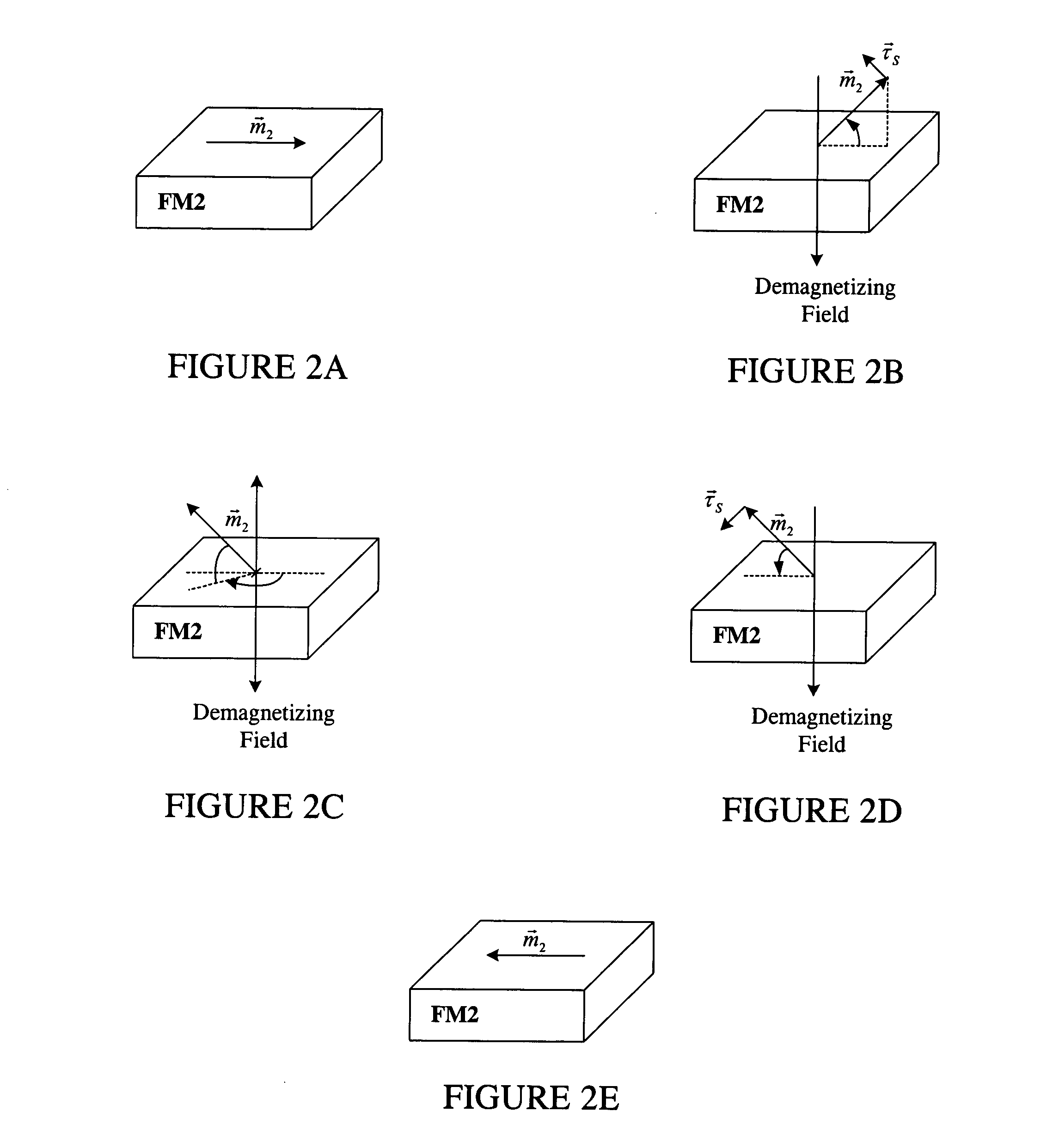
[0015] This demagnetizing field forces the magnetization vector of the free magnetic layer to precess, i.e., for the magnetization direction to rotate around the direction of the demagnetization magnetic field. The demagnetizing field also determines the rate of precession. A large demagnetizing field results in a high precession rate, which is an optimal condition for fast magnetic switching. An advantage of this magnetic device is that random fluctuating forces or fields are not necessary to initiate or control the magnetic response of the layers.

Problems solved by technology

This cross-talk will limit the density of the memory and / or cause errors in memory operations.
Further, the magnetic fields generated by such wires are limited to about 0.1 Tesla at the position of the electrodes, which leads to slow device operation.
Importantly, conventional memory designs also use stochastic (random) processes or fluctuating fields to initiate the switching events, which is inherently slow and unreliable (see, for example, R. H. Koch et al., Phys. Rev. Lett. 84, 5419 (2000)).
However, the proposed mechanism was purely theoretical.
However, the proposed devices are slow and rely on fluctuating magnetic fields and stochastic processes to initiate magnetization switching.
Further, large current densities are needed to switch the devices.
However, the devices proposed were unreliable, as there was little consistency with regard to device characteristics.

Method used


Image

  • High speed low power magnetic devices based on current induced spin-momentum transfer
  • High speed low power magnetic devices based on current induced spin-momentum transfer
  • High speed low power magnetic devices based on current induced spin-momentum transfer

Examples


example

[0069] The operation of the magnetic device was simulated using Landau-Lifzshitz Gilbert equations including a spin-transfer torque.

[0070]FIG. 8 shows the amplitude of the current input applied to the magnetic memory device starting at an initial time t=0 and ending at t=30 picoseconds. This current input comprises two current pulses similar to the current input shown in FIGS. 3A and 6A.

[0071] A 16-picosecond positive current pulse is applied to the magnetic memory device to start the precession of the magnetization vector {right arrow over (m)}2 of the free magnetic layer FM2. After this 16-picosecond current pulse, a 14-picosecond negative current pulse is applied to the magnetic memory device to stop the precession of the magnetization vector {right arrow over (m)}2 of the free magnetic layer FM2 to achieve a desired state of the magnetization vector {right arrow over (m)}2. For magnetic memory devices, the precession is stopped after achieving a 180° rotation of the magnetizat...


PUM


Abstract

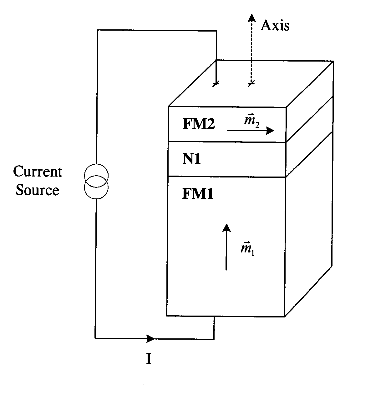
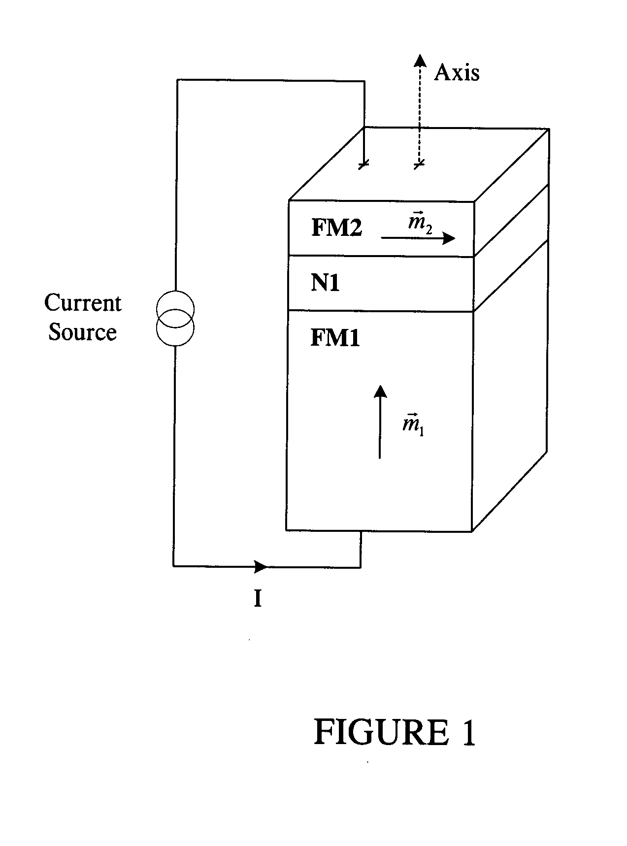
The present invention generally relates to the field of magnetic devices for memory cells that can serve as non-volatile memory. More specifically, the present invention describes a high speed and low power method by which a spin polarized electrical current can be used to control and switch the magnetization direction of a magnetic region in such a device. The magnetic device comprises a pinned magnetic layer with a fixed magnetization direction, a free magnetic layer with a free magnetization direction, and a read-out magnetic layer with a fixed magnetization direction. The pinned magnetic layer and the free magnetic layer are separated by a non-magnetic layer, and the free magnetic layer and the read-out magnetic layer are separated by another non-magnetic layer. The magnetization directions of the pinned and free layers generally do not point along the same axis. The non-magnetic layers minimize the magnetic interaction between the magnetic layers. A current is applied to the device to induce a torque that alters the magnetic state of the device so that it can act as a magnetic memory for writing information. The resistance, which depends on the magnetic state of the device, is measured to thereby read out the information stored in the device.

Description

FIELD OF THE INVENTION [0001] The present invention generally relates to magnetic devices used in memory and information processing applications, such as giant magnetoresistance (GMR) devices. More specifically, the present invention describes a high speed and low power method by which a spin polarized electrical current can be used to control and switch the direction of magnetization of a magnetic region in such a device. BACKGROUND OF THE INVENTION [0002] Magnetic devices that use a flow of spin-polarized electrons are of interest for magnetic memory and information processing applications. Such a device generally includes at least two ferromagnetic electrodes that are separated by a non-magnetic material, such as a metal or insulator. The thicknesses of the electrodes are typically in the range of 1 nm to 50 nm. If the non-magnetic material is a metal, then this type of device is known as a giant magnetoresistance or spin-valve device. The resistance of the device depends on the ...

Claims


Application Information

Patent Timeline
IPC IPC(8): G11C11/15G11C11/16H01F10/32H01L43/08
CPCB82Y10/00B82Y25/00H01F10/325H01L29/82H01F10/123G11C11/161G11C11/5607H01F10/3286H01L43/08G11C11/1673G11C11/1675H10N50/10
Inventor KENT, ANDREWGONZALEZ GARCIA, ENRIQUEOZYILMAZ, BARBAROS
Owner NEW YORK UNIVERSITY
Learn More