
Method and apparatus to form a reworkable seal on an electronic module

Inactive Publication Date: 2005-02-17
INTELLECTUAL DISCOVERY INC
View PDF7 Cites 18 Cited by
  • Summary
  • Abstract
  • Description
  • Claims
  • Application Information

AI Technical Summary

Benefits of technology

[0009] Land grid array (LGA) connectors are used to attach circuit modules to printed circuit boards that present an array of noble metal or semi-noble metal plated contacts to not only effect a rel

Problems solved by technology

Solder interconnection technology, traditionally used to interconnect smaller modules, is generally inapplicable to larger modules because of premature solder interconnect failures which violate reliability requirements.
Moreover a module interconnected by solder interconnections is not easily replaced in the field.
Mechanical attachment utilizing an array of brazed pins on the chip carrier and a mating socket on the board has been used for large multi-chip modules, and is readily field replaceable, but has a limitation on interconnect area density which precludes applicability for most current applications.
Disassembly of an adhesively sealed module is difficult, time-consuming and expensive; may leave a portion of the adhesive seal affixed to the module; and may cause damage to either or both of the cap or module.
However, with an LGA interconnect no structure can extend below the I / O pad surface without mechanically interfering with the printed circuit board (PCB).
Moreover, utilization of the bottom surface reduces the area available for the input / output (I / O) pads.
A clamping surface has been formulated by grinding a flange into the chip carrier or module, but this results in a significantly larger carrier by about 5-10 mm and incurs significant additional expense.

Method used


Image

  • Method and apparatus to form a reworkable seal on an electronic module
  • Method and apparatus to form a reworkable seal on an electronic module
  • Method and apparatus to form a reworkable seal on an electronic module

Examples


Embodiment Construction

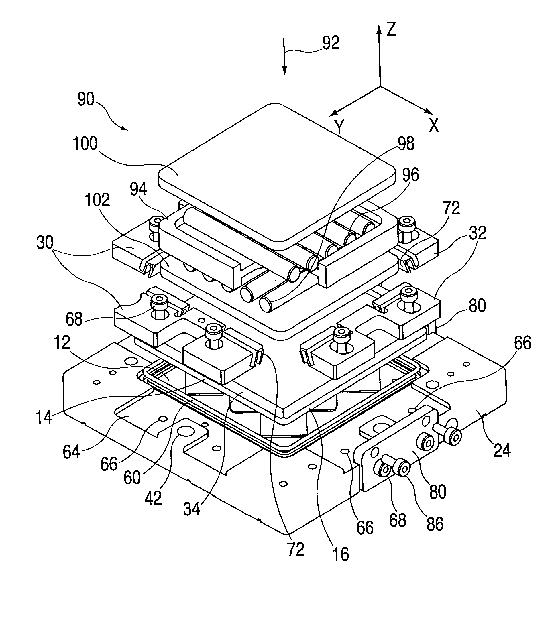
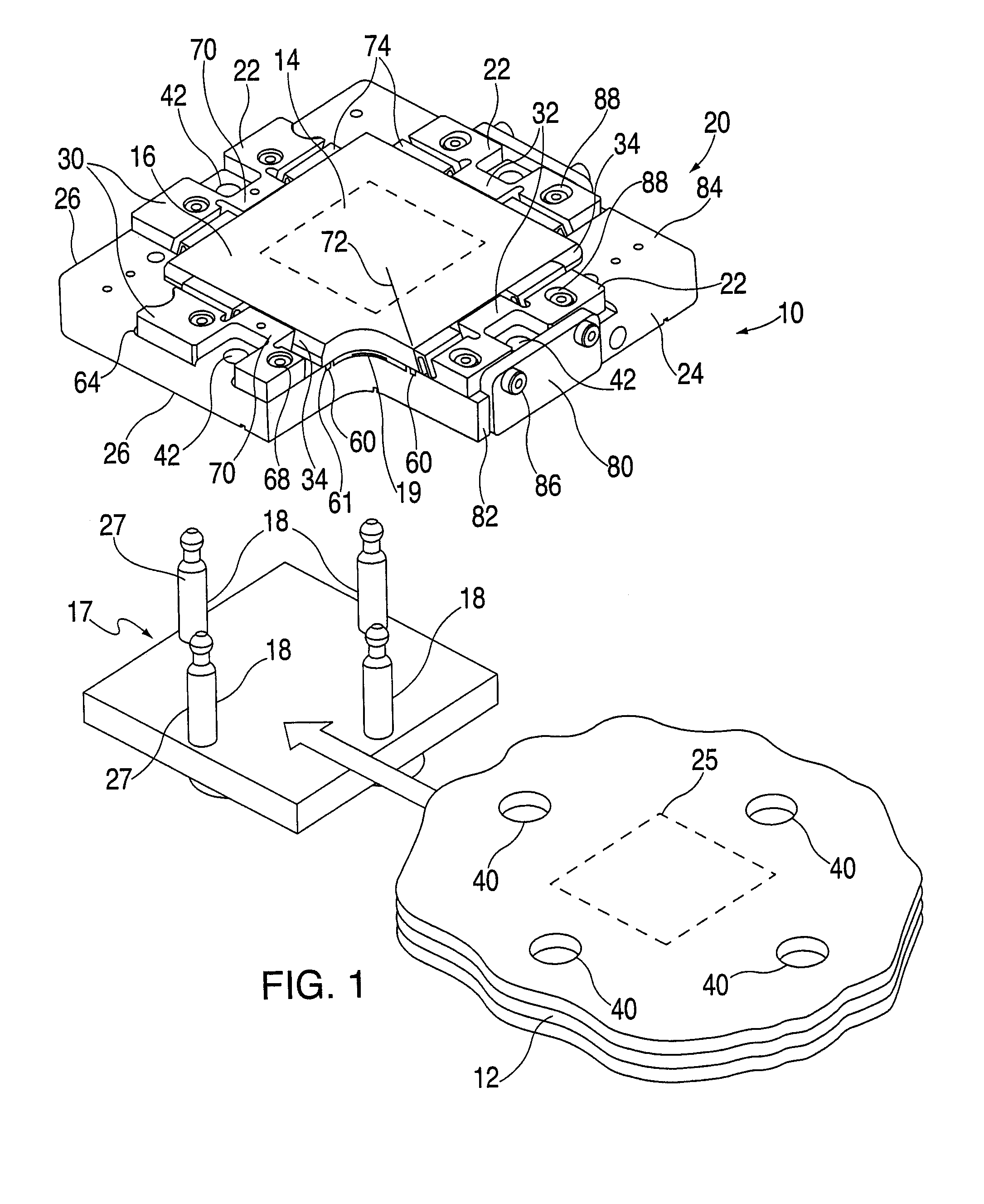
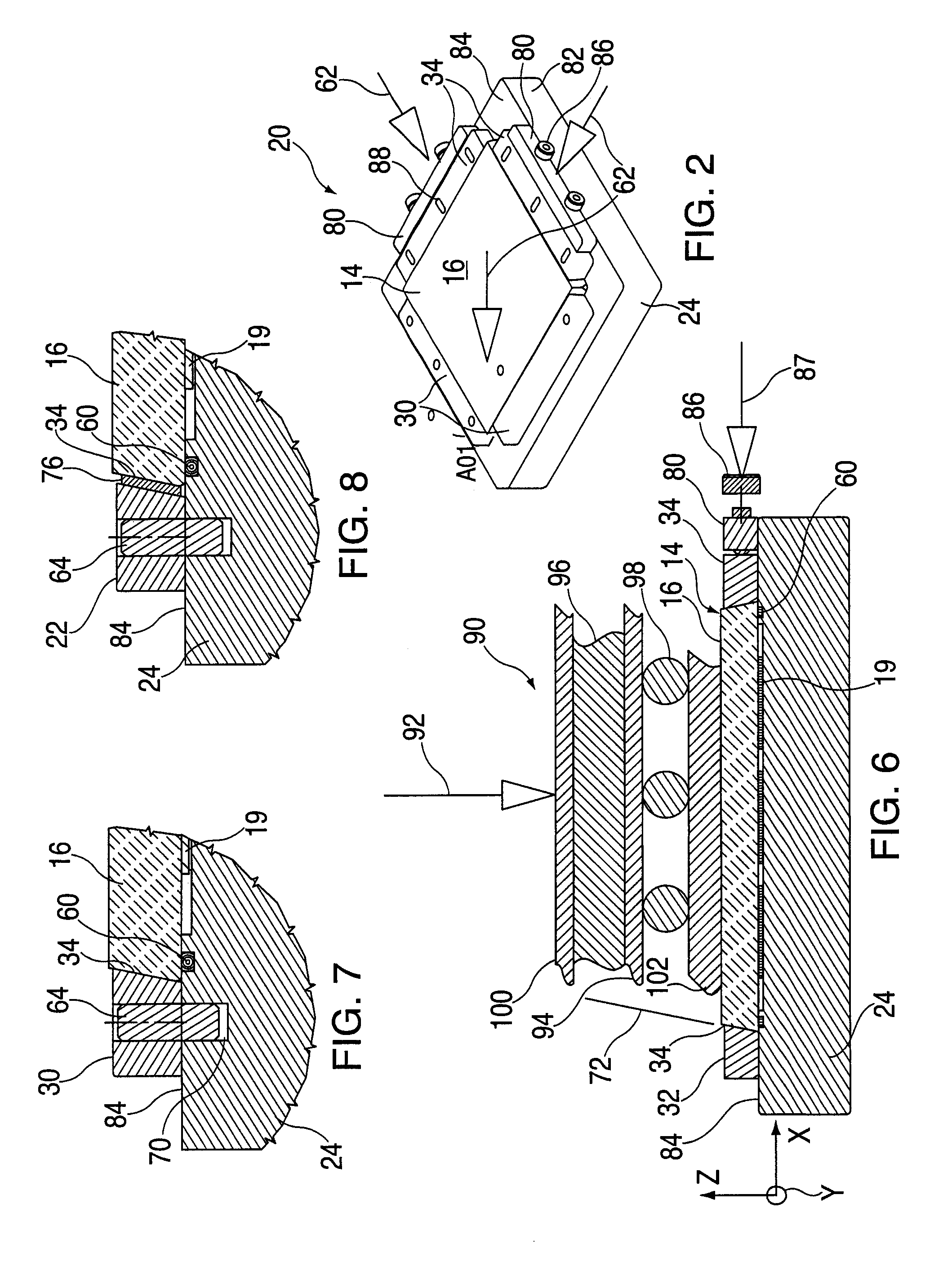
[0019] Referring to the drawings, FIG. 1 is an exploded view of an assembly 10 having an electronic module, or module, 20 and printed circuit board (PCB) 12 which are interconnected by a land grid array (LGA) connector assembly or socket (shown with dashed lines). Circuit module 14 includes a substrate 16 to which multiple chips 19 are affixed thereto. The assembly 10 includes a rigid and planar stiffener 17 with alignment pins 18, and cap assembly 20 having four tapered side loaders or sides 22. As shown, a circuit module 14 is situated between a cap assembly 20 and printed circuit board 12. Cap assembly 20 has a frame portion that includes an opening defined by a cap 24 in which circuit module 14 is received. The opening in cap 24 is bounded on two intersecting sides by walls 26 in which each includes a fixed tapered side loader 30 disposed. Each fixed tapered side loader 30 is abutted by circuit module side walls configured in substrate 16 to align the module with respect to the ...


PUM


Abstract

A system and method to form a reworkable compression seal between an electronic module and a cap are disclosed. The system and method include an electronic module having a tapered edge configured on at least a portion of the edge defining a perimeter of the electronic module and the cap configured with an opening to receive the electronic module therein. A compression seal is disposed with the cap and is configured to surround one or more chips or other electronic components on the electronic module to form a seal between the electronic module and the cap. A plurality of side loaders are operably coupled to the cap and aligned to receive the tapered edge on the electronic module. Each side loader is configured to engage the tapered edge and provide sufficient compressive force to the compression seal disposed between the electronic module and the cap.

Description

BACKGROUND OF INVENTION [0001] This disclosure relates generally to multi-chip electronic modules, more particularly those attached by land grid array (LGA) connectors. [0002] Current and future high performance computer systems and server systems rely on both large scale packaging of multiple high density interconnect modules and boards that must be upgraded in service. Solder interconnection technology, traditionally used to interconnect smaller modules, is generally inapplicable to larger modules because of premature solder interconnect failures which violate reliability requirements. Moreover a module interconnected by solder interconnections is not easily replaced in the field. Mechanical attachment utilizing an array of brazed pins on the chip carrier and a mating socket on the board has been used for large multi-chip modules, and is readily field replaceable, but has a limitation on interconnect area density which precludes applicability for most current applications. A mecha...

Claims


Application Information

Patent Timeline
IPC IPC(8): H01L21/50
CPCH01L21/50
Inventor MESSINA, GAETANO P.COICO, PATRICK A.GOLDMANN, LEWIS S.INDYK, RICHARD F.JAMBRIH, VLADIMIRZITZ, JEFFREY A.
Owner INTELLECTUAL DISCOVERY INC
Learn More