
Image forming apparatus

Inactive Publication Date: 2005-02-10
RICOH KK
View PDF14 Cites 19 Cited by
  • Summary
  • Abstract
  • Description
  • Claims
  • Application Information

AI Technical Summary

Benefits of technology

It is an object of the present invention to provide an image forming apparatus capable of accurately obviating toner scattering and blur ascribable to image transfer to thereby insure sharp images, an image transferring method, and toner for use in the image forming apparatus.
In an image forming apparatus configured to electrostatically transfer a toner image formed on an image carrier to a recording medium with image transferring means of the present invention, pressure is applied between the image carrier and the image transferring means. Toner is provided with relatively high hardness in accordance with the pressure beforehand. Image transfer is effected by reducing a potential difference between the image carrier and the recording medium while maintaining an electric field around the toner the same.

Problems solved by technology

Particularly, development and image transfer noticeably deteriorate image quality, as known in the art.
Therefore, it is likely that the toner deposits on the photoconductive element over a larger area than the latent image or that the toner image is blurred due to rubbing of carrier grains.
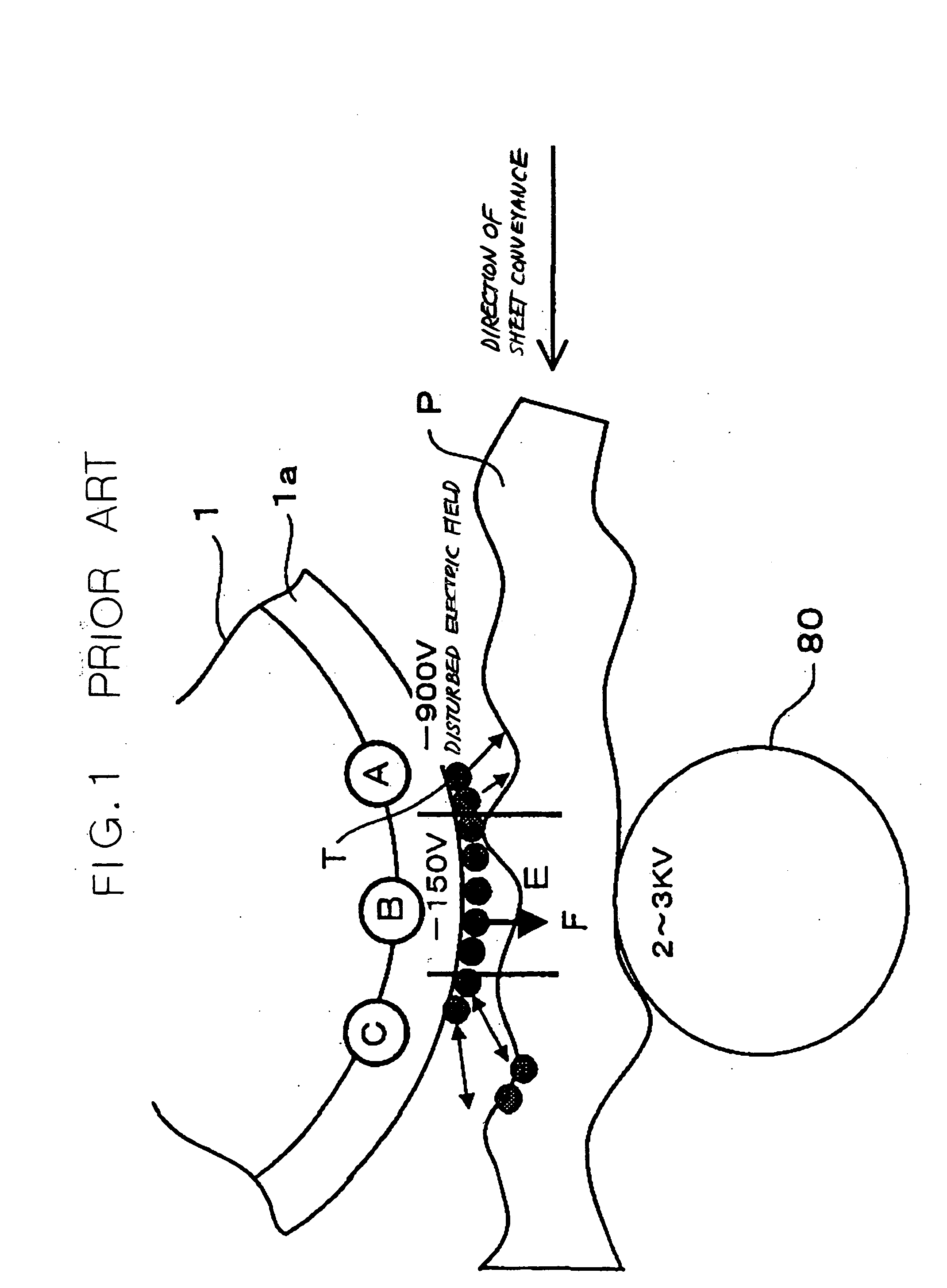
The problem with image transfer is that the toner is electrostatically scattered at positions preceding and following the position where the sheet and photoconductive element contact each other or that the toner image is blurred.
However, the capsule toner and press roller scheme is not desirable because capsule toner has various problems in practical use.
Particularly, development and fixation are not compatible with each other while cost is excessively high.
While toner produced by polymerization has recently been proposed to uniform image quality, toner scattering, blur and other problems particular to image transfer and ascribable to discharge are left unsolved.

Method used


Image

  • Image forming apparatus
  • Image forming apparatus
  • Image forming apparatus

Examples


examples 1 and 2

of the illustrative embodiment will be described hereinafter.

example 1

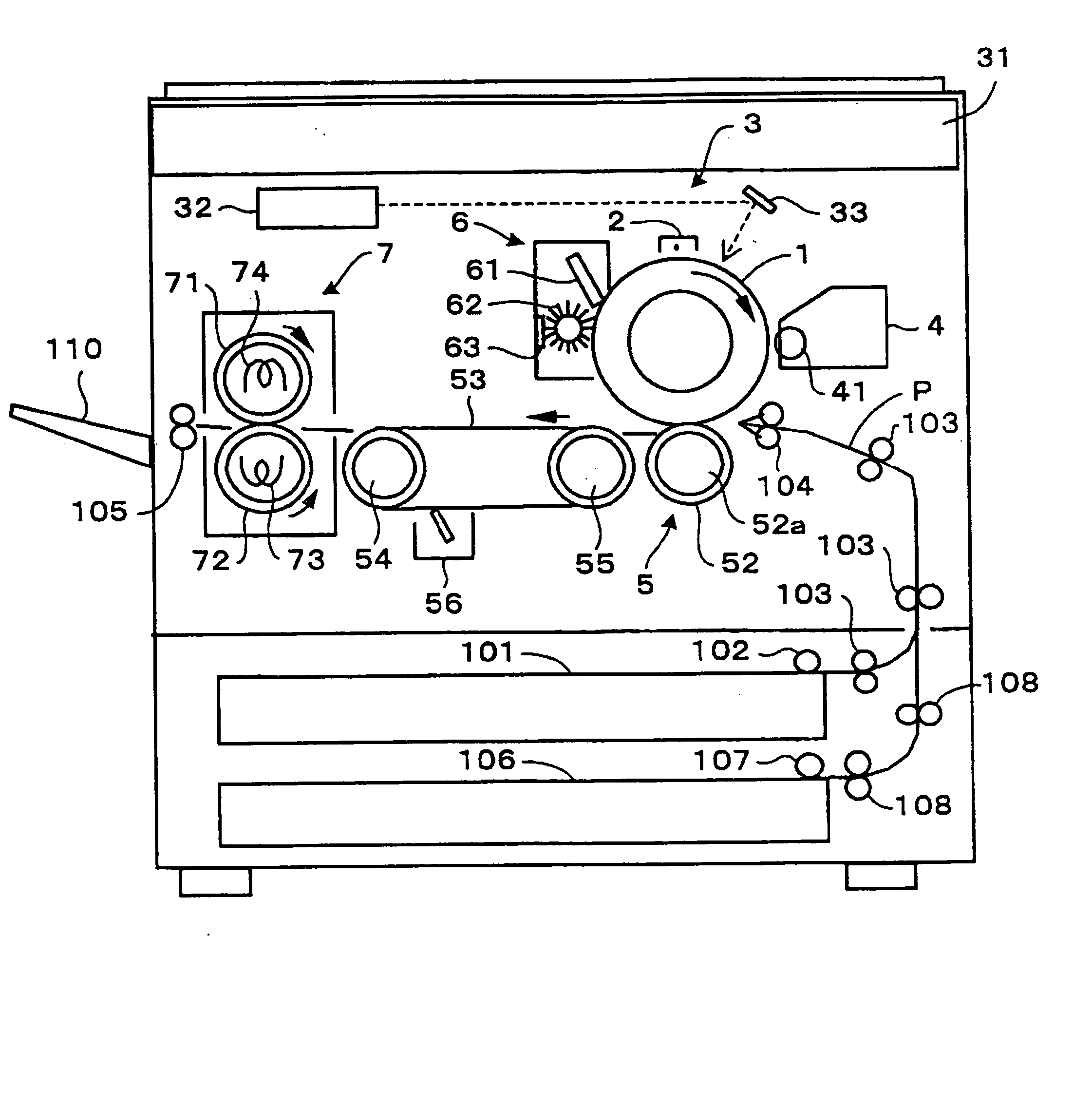
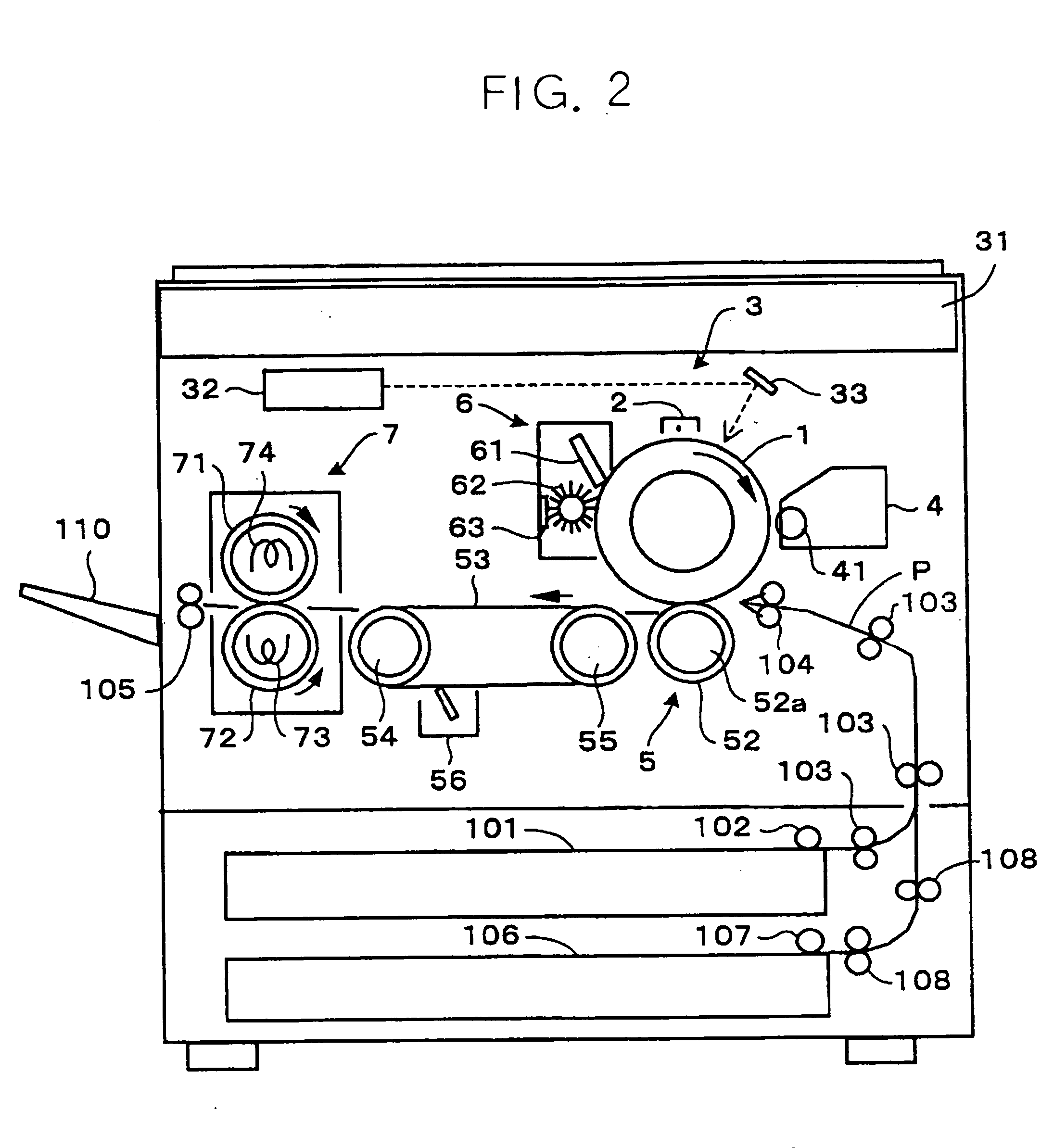
Imagio MF7070 with the modified image transfer section was used for estimation. To stabilize contact of the drum 1 and image transfer roller 52, a rubber layer or elastic layer with hardness of 65° in Asker C scale under a load of 1 kg and resistance of 1×10⁷ Ω·cm was formed on the surface of the image transfer roller 52. The test chart of FIG. 6 was printed with the image transfer pressure implemented by the springs 52d, FIG. 3, being set at 0.5 N / cm, 1.0 N / cm, 5.0 N / cm and 10.0 N / cm. At the same time, the voltage applied between the image transfer roller 52 and the drum 1 was so controlled as to establish current levels of 0.03 μA / cm, 0.05 μA / cm, 0.2 μA / cm and 0.3 μA / cm. Use was made of sheets Type 6000 and a developer having Prescription No. 8 stated earlier.

FIGS. 10, 11 and 12 list the results of estimation of image transfer ratio, toner scattering and local omission, respectively. It has been customary to use current of about 0.3 μA / cm to 0.4 μA / cm and pressure of about 1 N / c...

experiment 2

[Experiment 2]

Developers with Prescriptions 1 through 8 stated earlier were produced by the same method as in Example 1. Carrier grains were implemented by spherical ferrite grains having a weight-mean grain size of 50μ and coated with silicone resin. The carrier content of each developer was 5.0 wt. %. The test chart of FIG. 6 was printed by the pressure of 3 N / cm and current of 0.1 μA / cm. Again, sheets Type 6000 were used. Estimation was made in terms of image transfer ratio and toner scattering. The results of estimation are shown in FIG. 13.

As FIG. 13 indicates, the coefficient of friction of the drum 1 effects the image transfer ratio more in relation to the cohesion of toner than alone. If the volumetric resistance of toner is low, it effects the image transfer ratio, but does not noticeably effect toner scattering. As for toner scattering, toner hardness should be high, but no improvements are achievable unless pressure is varied in relation to toner cohesion. In the case ...


PUM


Abstract

In an image forming apparatus configured to electrostatically transfer a toner image formed on an image carrier to a recording medium with image transferring means of the present invention, pressure is applied between the image carrier and the image transferring means. Toner is provided with relatively high hardness in accordance with the pressure beforehand. Image transfer is effected by reducing a potential difference between the image carrier and the recording medium while maintaining an electric field around the toner the same.

Description

BACKGROUND OF THE INVENTION 1. Field of the Invention The present invention relates to a copier, printer, facsimile apparatus or similar image forming apparatus and more particularly to an image transferring method and toner for an image forming apparatus. 2. Description of the Background Art Generally, an electrophotographic image forming apparatus needs a number of image forming steps. A copier, for example, converts a document image to an electric signal with a scanner or optics while a printer directly inputs a document image in a plotter in the form of a signal. Writing means scans a photoconductive element or image carrier with a laser beam in accordance with the electric signal to thereby form a latent image. Toner or similar fine colored powder is deposited on the latent image to thereby produce a corresponding toner image. The toner image is then transferred from the photoconductive element to a sheet or recording medium. Today, it is a common practice to sequentially t...

Claims


Application Information

Patent Timeline
IPC IPC(8): G03G9/08G03G15/16
CPCG03G2215/1614G03G15/1675
Inventor KOICHI, YASUSHIAOKI, MITSUOSHU, BINGSUZUKI, KOJIWATANABE, SHIGERUKASAI, TADASHITAKAHASHI, YUTAKA
Owner RICOH KK
Learn More