
Scanning device, laser projector, and optical device

Inactive Publication Date: 2005-02-03
SEIKO EPSON CORP
View PDF7 Cites 5 Cited by
  • Summary
  • Abstract
  • Description
  • Claims
  • Application Information

AI Technical Summary

Benefits of technology

[0006] In consideration of the above-mentioned problems, the invention provides a scanning device, a laser projector and an optical device that are capable of accomplishing the wide scanning area in a simple manner
[0007] In order to address the above-mentioned problem and accomplish the above, a scanning device of an aspect of the invention includes a scanning part scanning laser light like a beam and a scanning optical system on which the laser light from the scanning part is incident. The scanning optical system includes a first lens group having a positive refracting power and a second lens group, in this order, from the scanning part. The scanning part is disposed in the vicinity of a focal position that is located at an incident side of the laser light of the first lens group. The first lens group and the second lens group are disposed such that the focal position that is located at an exiting side of the laser light of the first lens group is approximately coincident with the focal position that is located at an incident side of the laser light of the second lens group. An absolute value of the value that is calculated by dividing the focal distance of the first lens group by the focal distance of the second lens group is larger than 1. Accordingly, a collimated light that is incident on the first lens group in the scanning optical system emits from the second lens group as the collimated light. In this way, the scanning optical system forms an afocal system. Also, the value that is calculated by dividing the focal distance of the first lens group by the focal distance of the second lens group is proportional to an angular magnification of the scanning optical system. Thus, the scanning optical system has the angular magnification that is larger than 1. Therefore, in the scanning optical system, the laser light entered from the scanning part is converted into the laser light that has a larger exiting angle than the incident angle and exits. As a result, a wider scanning area can be accomplished in a simple manner.
[0011] A laser projector of an aspect of the invention includes a laser light source providing laser light like a beam, a scanning part scanning the laser light in a two-dimensional direction, and a scanning optical system on which the laser light from the scanning part is incident. The scanning optical system includes a first lens group having a positive refracting power and a second lens group, in this order, from the scanning part. The scanning part is disposed in the vicinity of a focal position, that is located at an incident side of the laser light of the first lens group. The first lens group and the second lens group are disposed such that the focal position that is located at an exiting side of the laser light of the first lens group, is approximately coincident with the focal position that is located at an incident side of the laser light of the second lens group. An absolute value of the value that is calculated by dividing the focal distance of the first lens group by the focal distance of the second lens group is larger than 1. As for the above described “in this order from the scanning part”, it can be defined “in the order from the incident of the laser light on the scanning optical system, regardless of the position of the scanning part.” Accordingly, a collimated light that is incident on the first lens group in the scanning optical system exits from the second lens group as the collimated light. In this way, the scanning optical system forms an afocal system. Also, the value that is calculated by dividing the focal distance of the first lens group by the focal distance of the second lens group is proportional to an angular magnification of the scanning optical system. Thus, the scanning optical system has the angular magnification that is larger than 1. Therefore, in the scanning optical system, the laser light entered from the scanning part is converted into the laser light that has a larger exiting angle than the incident angle and exits. Consequently, this makes it possible to accomplish a wide projection screen with the condition where the projection distance between the scanning optical system and the screen is shortened.
[0014] An optical device of an aspect of the invention includes a laser light source providing laser light like a beam, a scanning part scanning the laser light, and a scanning optical system on which the laser light from the scanning part is incident. The scanning optical system includes a first lens group having a positive refracting power and a second lens group, in this order, from the scanning part. The scanning part is disposed in the vicinity of a focal position that is located at an incident side of the laser light of the first lens group. The first lens group and the second lens group are disposed such that the focal position that is located at the laser light exiting side of the first lens group is approximately coincident with the focal position that is located at an incident side of the laser light of the second lens group. An absolute value of the value that is calculated by dividing the focal distance of the first lens group by the focal distance of the second lens group is larger than 1. As for the above described “in this order from the scanning part”, it means “in the order from the incident of the laser light on the scanning optical system, regardless of the position of the scanning part”. Also, according to the preferable aspect of the invention, it is preferable that the scanning part scanning in one-dimensional direction or two-dimensional direction. In the case where the optical device is a printer, for example, it is possible to shorten the distance between a photosensitive drum and the scanning optical system. As a result, a compact printer can be achieved.

Problems solved by technology

For example, in a laser projector that is equipped with the related art galvanomirror, it is difficult to obtain a large projection screen if the screen is placed close to the projector.
Also it results in an extremely small mirror.
Alternatively, if the electromagnetic actuator is used as a driver for the larger angular amount, this also increases the driving current tremendously.
Subsequently, it is difficult in a related art scanning optical system to accomplish a wide scanning area in a simple manner.

Method used


Image

  • Scanning device, laser projector, and optical device
  • Scanning device, laser projector, and optical device
  • Scanning device, laser projector, and optical device

Examples


first exemplary embodiment

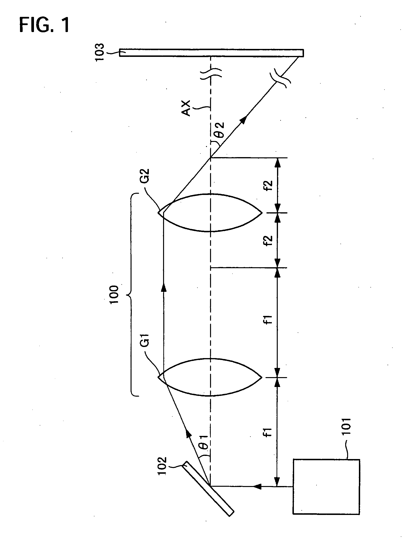
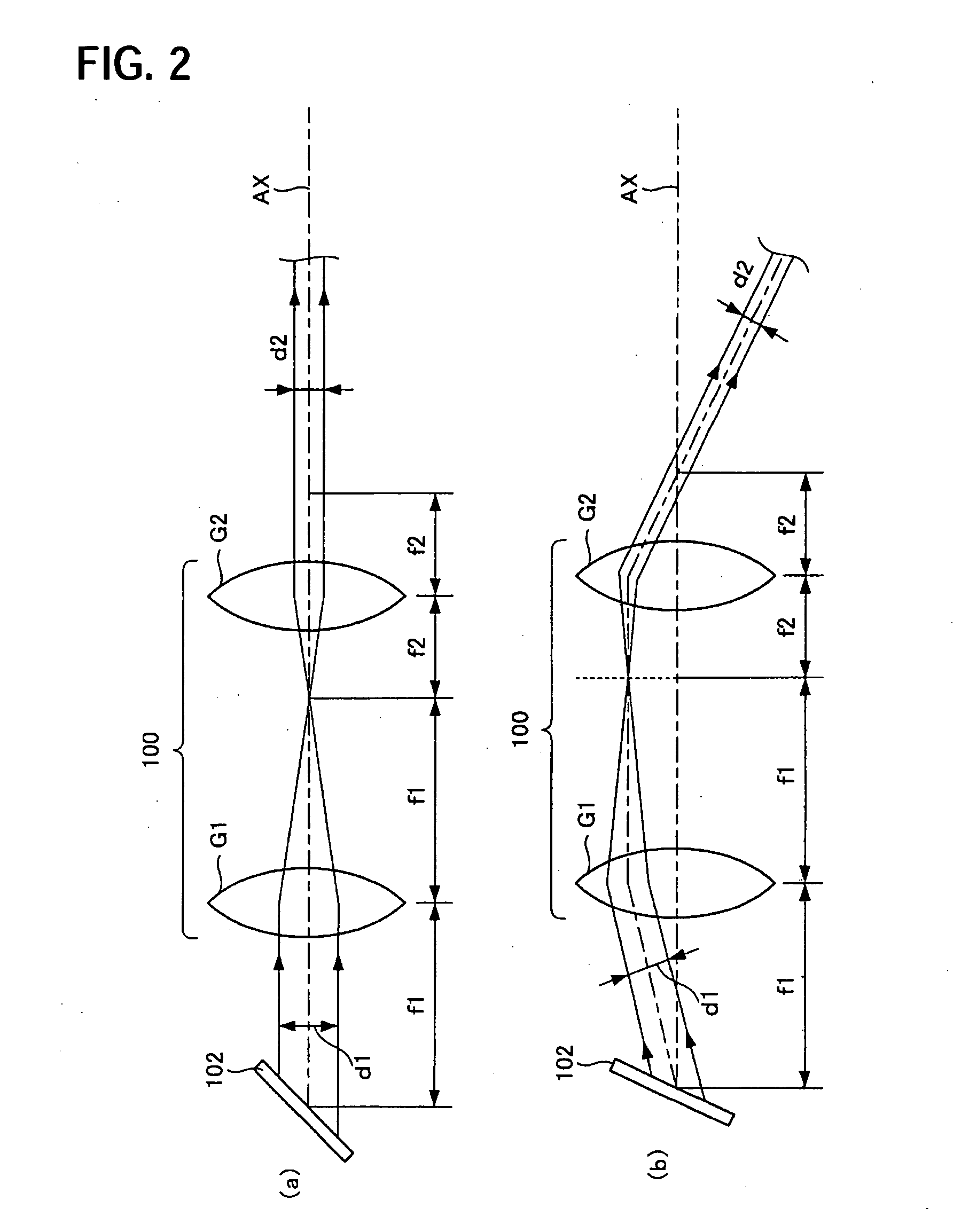
[0022]FIG. 1 is a schematic showing a rough construction of a scanning device of a first exemplary embodiment of the invention. Laser light, like a beam emitted from a laser light source 101, is incident on a galvanomirror 102, which plays a role of a scanning part 102. The galvanomirror 102 scans the laser light emitted from the laser light source 101 in a two-dimensional direction with a plane mirror that is rotated approximately two perpendicularly crossing directions. The laser light that has been scanned is incident on a scanning optical system 100. The scanning optical system includes a first lens group G1 having a positive refracting power and a second lens group G2 having the positive refracting power, in this order, from the scanning part 102. The first lens group has a focal distance f1 and the second lens group has a focal distance f2.

[0023] The galvanomirror 102 is disposed in the vicinity of a focal position that is located at an incident side of the laser light of the...

second exemplary embodiment

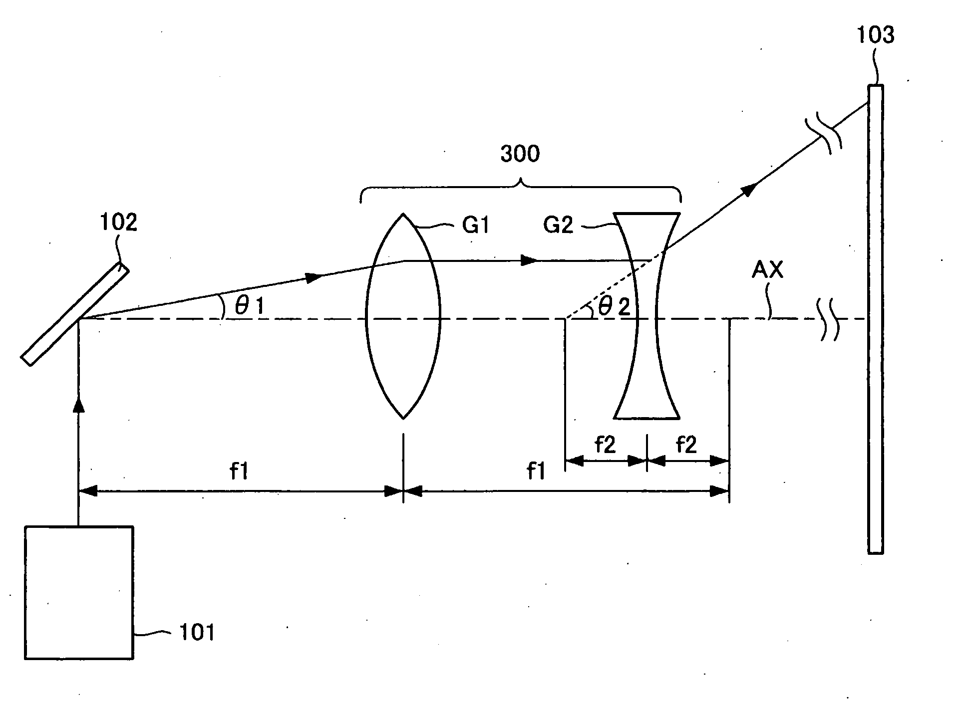
[0026]FIG. 3 is a schematic showing a rough construction of a scanning optical system 300 of a second exemplary embodiment of the invention. In the above-mentioned first exemplary embodiment, the second lens group has a positive refracting power. However, in this exemplary embodiment, the second lens group has a negative refracting power. The same label will be given to the part that is same as described in the above-mentioned first exemplary embodiment and overlapping explanations will be omitted. The scanning optical system 300 includes a scanning part 102, a first lens group G1 having a positive refracting power, and a second lens group G2 having a negative refracting power in this order from the scanning part 102 side. The first lens group has a focal distance f1 and the second lens group has a focal distance f2 (a negative value).

[0027] The galvanomirror 102, which plays a role of the scanning part 102, is disposed in the vicinity of a focal position that is located at an inci...

third exemplary embodiment

[0030]FIG. 5 is a schematic showing a rough construction of a laser projector 500 of a third exemplary embodiment of the invention. A first color laser light source 501R provides a red color laser light (hereinafter called “light R”) modulated in accordance with a picture signal. A second color laser light source 501G provides a green color laser light (hereinafter called “light G”) modulated in accordance with a picture signal. A third color laser light source 501B provides a blue color laser light (hereinafter called “light B”) modulated in accordance with a picture signal. Each color laser light source 501R, 501G, 501B is driven and controlled by a controller 503. Each color laser light source 501R, 501G, 501B and the controller 503 are accommodated in a laser unit 520. A semiconductor laser or a solid-state laser or the like can be used for each color laser light source 501R, 501G, 501B.

[0031] A dichroic mirror 502R transmits the light R and reflects the light G. Similarly, a d...


PUM


Abstract

A scanning device, a laser projector and an optical device that are capable of accomplishing a wide scanning area in a simple manner include a galvanomirror that is a scanning part scans a laser light in a two-dimensional direction. The laser light from the galvanomirror is incident on a scanning optical system. The scanning optical system includes a first lens group having a positive refracting power and a second lens group having the positive refracting power in this order from the scanning part. The galvanomirror is disposed in the vicinity of a focal position that is located at an incident side of the laser light of the first lens group. The first lens group and second lens group are disposed such that the focal position that is located at an exiting side of the laser light of the first lens group is approximately coincident with the focal position that is located at an incident side of the laser of the second lens group. An absolute value of the value that is calculated by dividing the focal distance of the first lens group by the focal distance of the second lens group is larger than 1.

Description

BACKGROUND OF THE INVENTION [0001] 1. Field of Invention [0002] The present invention relates to a scanning device, especially a device to scan laser light, like a beam, a laser projector and an optical device. [0003] 2. Description of Related Art [0004] In the related art, a galvanomirror or the like are used as an optical system to scan a laser light from a laser light source in a two-dimensional direction. The galvanomirror scans the laser light in the two-dimensional direction with a plane mirror that is rotated approximately two perpendicularly crossing directions by a drive, such as an electrostatic actuator or the like. Also, a micro machine technique makes it easy to produce the galvanomirror that is capable of operating at a high speed. SUMMARY OF THE INVENTION [0005] However, the related art galvanomirror is merely capable of rotating by a small angular amount. Therefore, when the laser light is scanned in the two-dimensional direction in a predetermined plane, such as a s...

Claims


Application Information

Patent Timeline
IPC IPC(8): B41J2/47B41J15/14B41J27/00G02B26/08G02B26/10H04N5/74H04N9/31
CPCB41J2/471H04N9/3129G02B26/105G02B26/123
Inventor YONEKUBO, MASATOSHI
Owner SEIKO EPSON CORP
Learn More