Structure for transmitting power of a motorcycle engine, and a method of assembly of said structure

Inactive Publication Date: 2006-11-14
HONDA MOTOR CO LTD
View PDF8 Cites 0 Cited by
  • Summary
  • Abstract
  • Description
  • Claims
  • Application Information

AI Technical Summary

Benefits of technology

[0013]In the present invention, the intermediate shaft driven gear and the intermediate shaft driving gear are disposed on the intermediate shaft outside the crankcase. Therefore, it is possible to mount all of the shafts, namely the crankshaft, the intermediate shaft, the main input shaft of the transmission, and the output shaft of the transmission, on the crankcase, and then to easily mount all of the gears for transmitting the power from one of these shafts to another at positions outside the crankcase. This configuration results in improved in workability of assembly of the members involved. Further, since the intermediate shaft driven gear and the intermediate shaft driving gear are mounted on the intermediate shaft in two steps, it is possible to freely set a speed reduction ratio. Moreover, the configuration of this invention shortens the distance between the intermediate shaft and the crankshaft, and the distance between the intermediate shaft and the input shaft of the transmission.
[0014]In the present invention, since the balancer weight is disposed on the intermediate shaft at the portion projecting outside the crankcase, unlike conventional embodiments in which the balancer weight is disposed inside the crankcase, the balancer weight can be mounted without regard for the clearance between itself and a crank web, thereby increasing layout flexibility. In addition, since the balancer weight is mounted at the position away from the center of the engine, it is possible to produce a greater effect for regulating lateral vibrations.
[0015]In the present invention, each of the intermediate shaft driven gear and the intermediate shaft driving gear is formed in a canceling structure, with each gear having a sub-gear. All four of these gears are then butted together and fixed in the thrust direction by means of a simple washer and nut, eliminating the need for a special fixing structure, and hence simplifying the structure.

Problems solved by technology

Further, if a balancer weight is mounted on the intermediate shaft inside the crankcase, restrictions are introduced into the layout, depending on the presence or absence of a clearance between the balancer web and a crank web.
Further, if a gear disposed on the intermediate shaft is used only as an idle gear, as Japanese Examined Patent Publication No. 7-94859 discloses, a free speed reduction ratio cannot be obtained and the distance between the intermediate shaft and the input shaft of the transmission is inevitably made greater.

Method used


Image

  • Structure for transmitting power of a motorcycle engine, and a method of assembly of said structure
  • Structure for transmitting power of a motorcycle engine, and a method of assembly of said structure
  • Structure for transmitting power of a motorcycle engine, and a method of assembly of said structure

Examples


Embodiment Construction

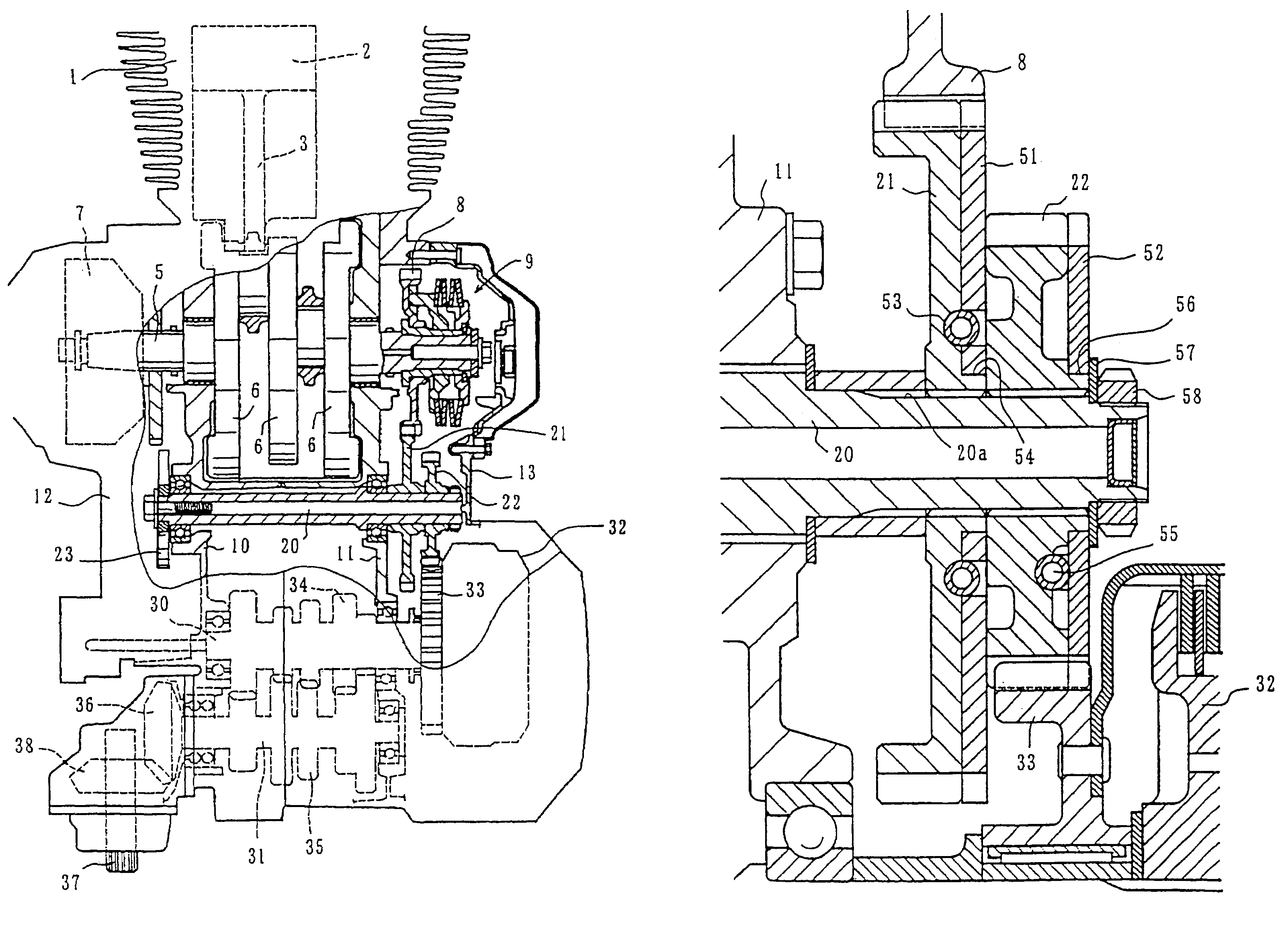
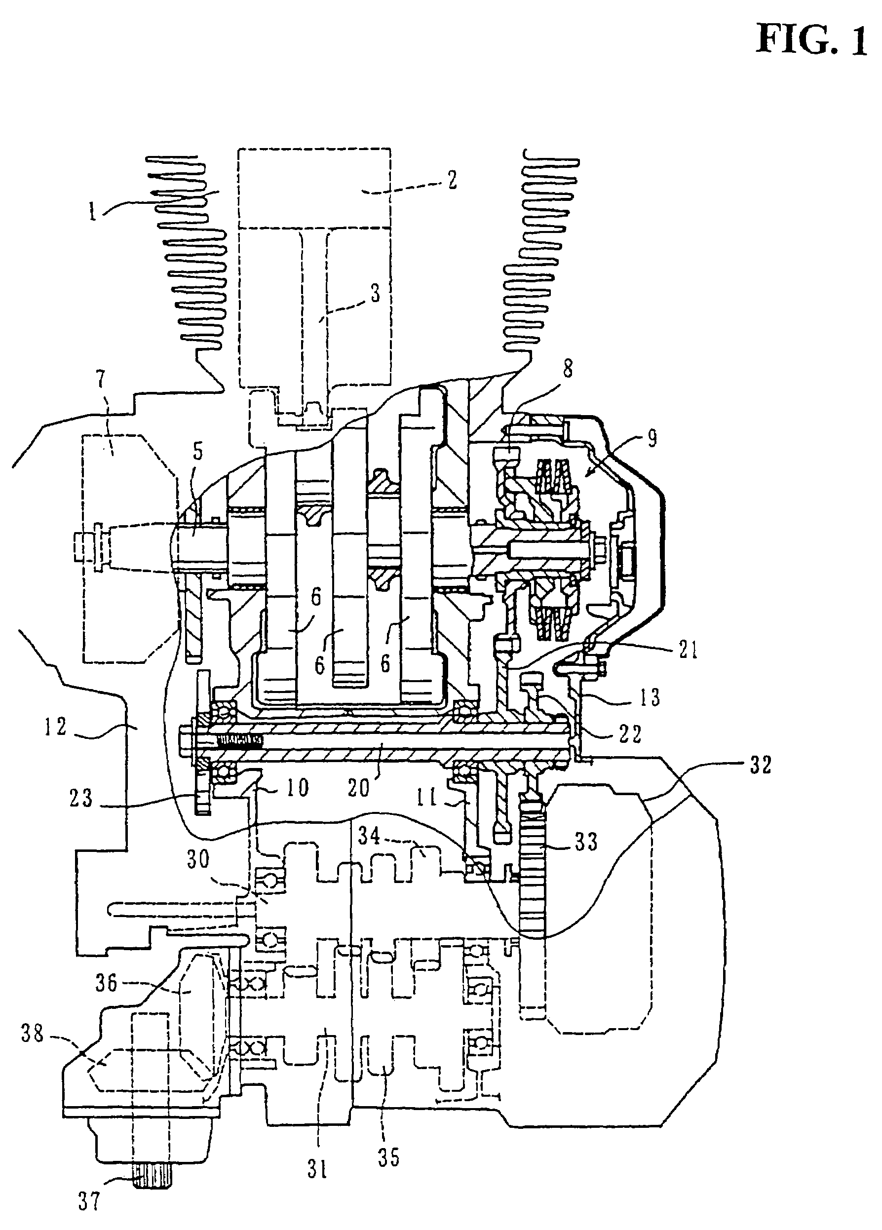
[0020]A first embodiment will be described in the following on the basis of FIG. 1, which shows a partially cutaway view of an engine to show a structure for transmitting the power of a V-shaped engine for a motorcycle. In FIG. 1, a V-shaped engine 1 is provided and includes a piston 2, a connecting rod 3, a crankshaft 5, and a crank web 6. On the one end of the crankshaft 5 is mounted a generator 7 and on the other end thereof are mounted a primary gear 8 and a primary damper 9 which is a torque damper.

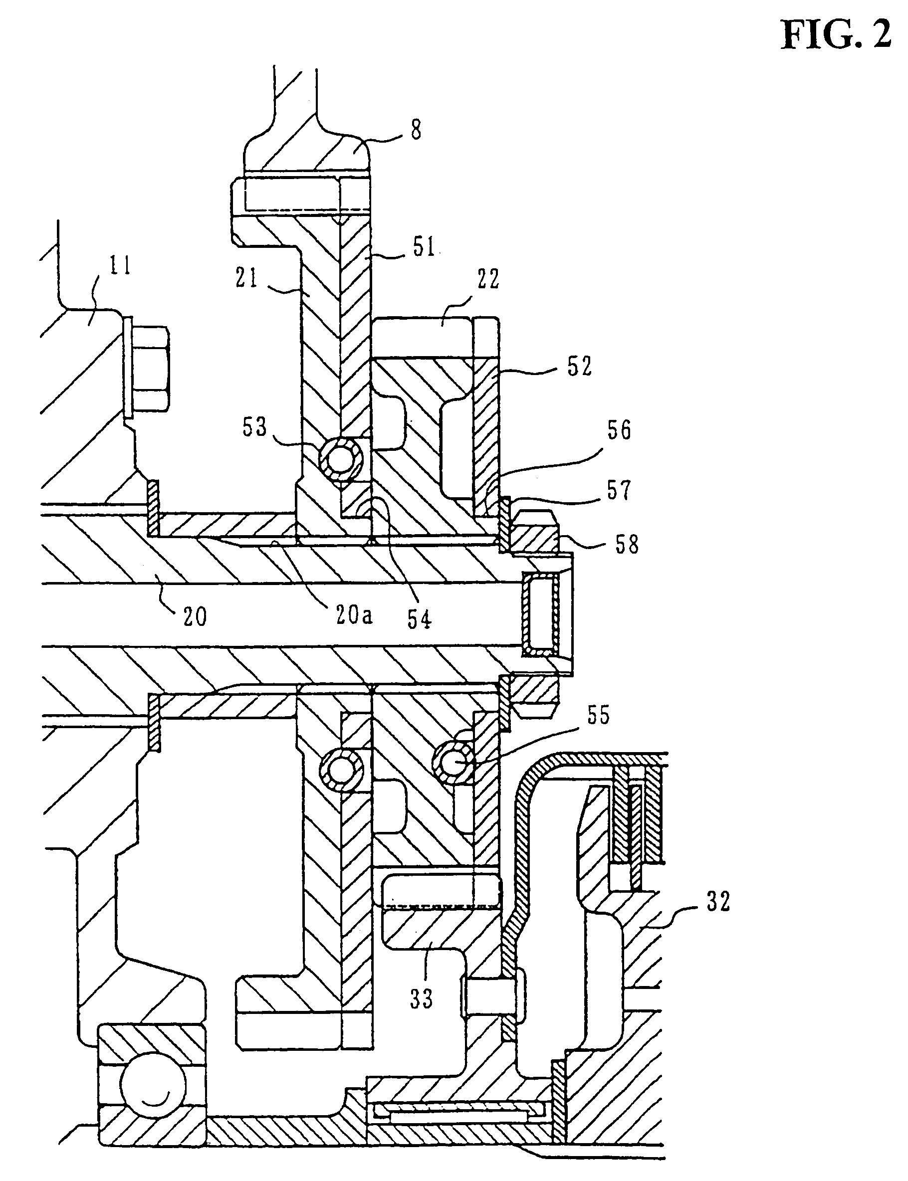
[0021]The crankshaft 5 is supported by a left case 10 and a right case 11 which constitute a crankcase. A reference numeral 12 designates a left case cover and a reference numeral 13 designates a right case cover. An intermediate shaft 20 is disposed in parallel to the crankshaft 5, and an intermediate shaft driven gear 21 engaging with the primary gear 8 is mounted on the end portion of the intermediate shaft 20 projecting outside the right case 11 and an intermediate driving gear 2...


PUM

PropertyMeasurementUnit
Weightaaaaaaaaaa
Poweraaaaaaaaaa

Abstract

A structure for transmitting the power of a motorcycle engine includes an intermediate shaft arranged between a crankshaft and an input shaft of a transmission, and a method for making the structure. The structure and the method have the objective of shortening the distances between these three shafts, improving workability of assembling, and providing freedom of setting a speed reduction ratio. An intermediate shaft driven gear and an intermediate shaft driving gear having a diameter smaller than the intermediate shaft driven gear and are mounted in two steps, with the former overlaid on the latter, on an end of the intermediate shaft projecting outside a right case. Similarly, the intermediate shaft driven gear is engaged with a primary gear of the crankshaft, and the intermediate shaft driving gear is engaged with a primary driven gear of the input shaft at a location outside the right case.

Description

CROSS-REFERENCE TO RELATED APPLICATIONS[0001]This application is a Divisional of application Ser. No. 09 / 949,754, filed on Sep. 12, 2001, now U.S. Pat. No. 6,715,376, the entire contents of which are hereby incorporated by reference and for which priority is claimed under 35 U.S.C. § 120; and this application claims priority of Application No. 2000-277065 filed in Japan on Sep. 12, 2000 under 35 U.S.C. § 119. Application No. 2000-277065 is now U.S. Pat. No. 6,715,376.BACKGROUND OF THE INVENTION[0002]1. Field of the Invention[0003]The present invention relates to a structure for transmitting the power of an engine in a motorcycle or the like and, in particular, to the structure in which an intermediate shaft is interposed between a crankshaft and the main input shaft of a transmission. The invention also relates to a process for assembling said structure.[0004]2. Description of Background Art[0005]A structure for transmitting the power of an engine using such an intermediate shaft is...

Claims


Application Information

Patent Timeline
IPC IPC(8): B21K3/00B60K17/04B62M7/00F02B61/02F16F15/26F16H37/04F16H55/17F16H55/18
CPCB62M7/00F02B61/02F16H37/043Y10T74/19647Y10T29/49464Y10T74/19651Y10T29/4984Y10T29/49231Y10T74/19898
Inventor HOJYO, ATSUOINUI, HIROATSUKOHNO, NAOKIOKUBO, FUMIAKI
Owner HONDA MOTOR CO LTD
Why Eureka
Try Eureka