Micro-cantilever type probe card
- Summary
- Abstract
- Description
- Claims
- Application Information
AI Technical Summary
Benefits of technology
Problems solved by technology
Method used
Image
Examples
Embodiment Construction
[0040] Reference will now be made in detail to the present invention as illustrated in the accompanying drawings.
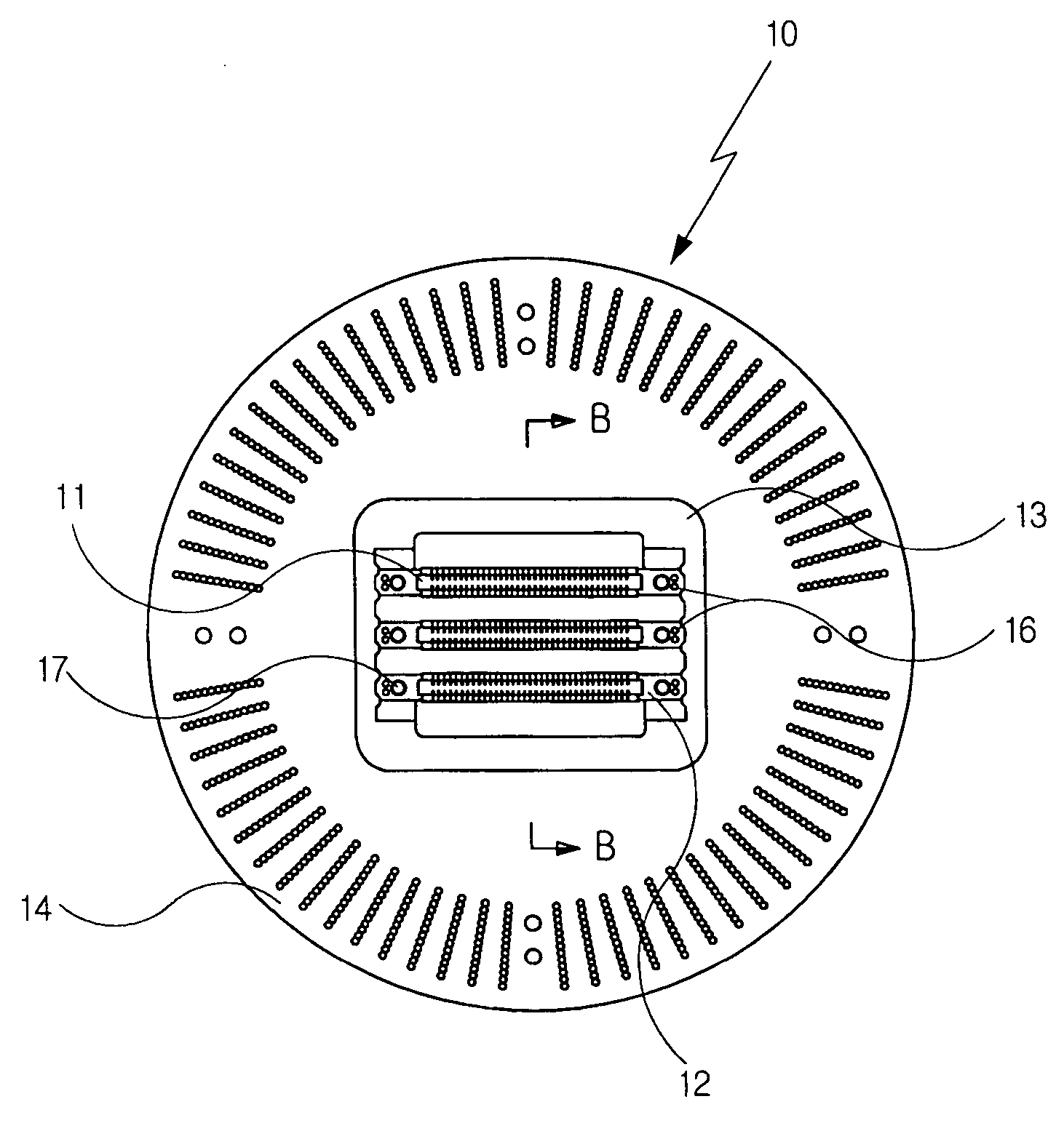
[0041]FIG. 4 is a plane figure of the probe card applied to the probe card structure of the present invention. FIG. 5 is a cross sectional view of the probe card along the line B-B in FIG. 4, FIG. 6 illustrates a disassembled probe card of FIG. 4.
[0042] Referring to FIGS. 4, 5 and 6, in the probe card (10) of the present invention, the probe sections (11) are fixed on the linear supporting structures (12) by adhesives (not illustrated). The supporting structures (12) are fixed on the rectangular frame shaped fixing structures (13) having a rectangular shaped hole. The fixing structure (13) is fixed on the center of the upper surface of the circular circuit board (14). A reinforcing plate (18) is installed on the lower surface of the circuit board (14). As illustrated in FIG. 8, the probe sections (11) and the circuit board (14) are electrically connected by the pogo pin...
PUM
 Abstract
Description
Claims
Application Information
 - R&D
- Intellectual Property
- Life Sciences
- Materials
- Tech Scout
- Unparalleled Data Quality
- Higher Quality Content
- 60% Fewer Hallucinations
Browse by: Latest US Patents, China's latest patents, Technical Efficacy Thesaurus, Application Domain, Technology Topic, Popular Technical Reports.
© 2025 PatSnap. All rights reserved.Legal|Privacy policy|Modern Slavery Act Transparency Statement|Sitemap|About US| Contact US: help@patsnap.com


