Surface-mounted LED and light emitting device
a technology of led and light emitting device, which is applied in the manufacture of semiconductor/solid-state devices, semiconductor devices, electrical devices, etc., can solve the problems of increased power loss of led, increased heat release, and increased heat loss of led, so as to improve heat structure, increase heat release efficiency, and enhance light emission efficiency
- Summary
- Abstract
- Description
- Claims
- Application Information
AI Technical Summary
Benefits of technology
Problems solved by technology
Method used
Image
Examples
first embodiment
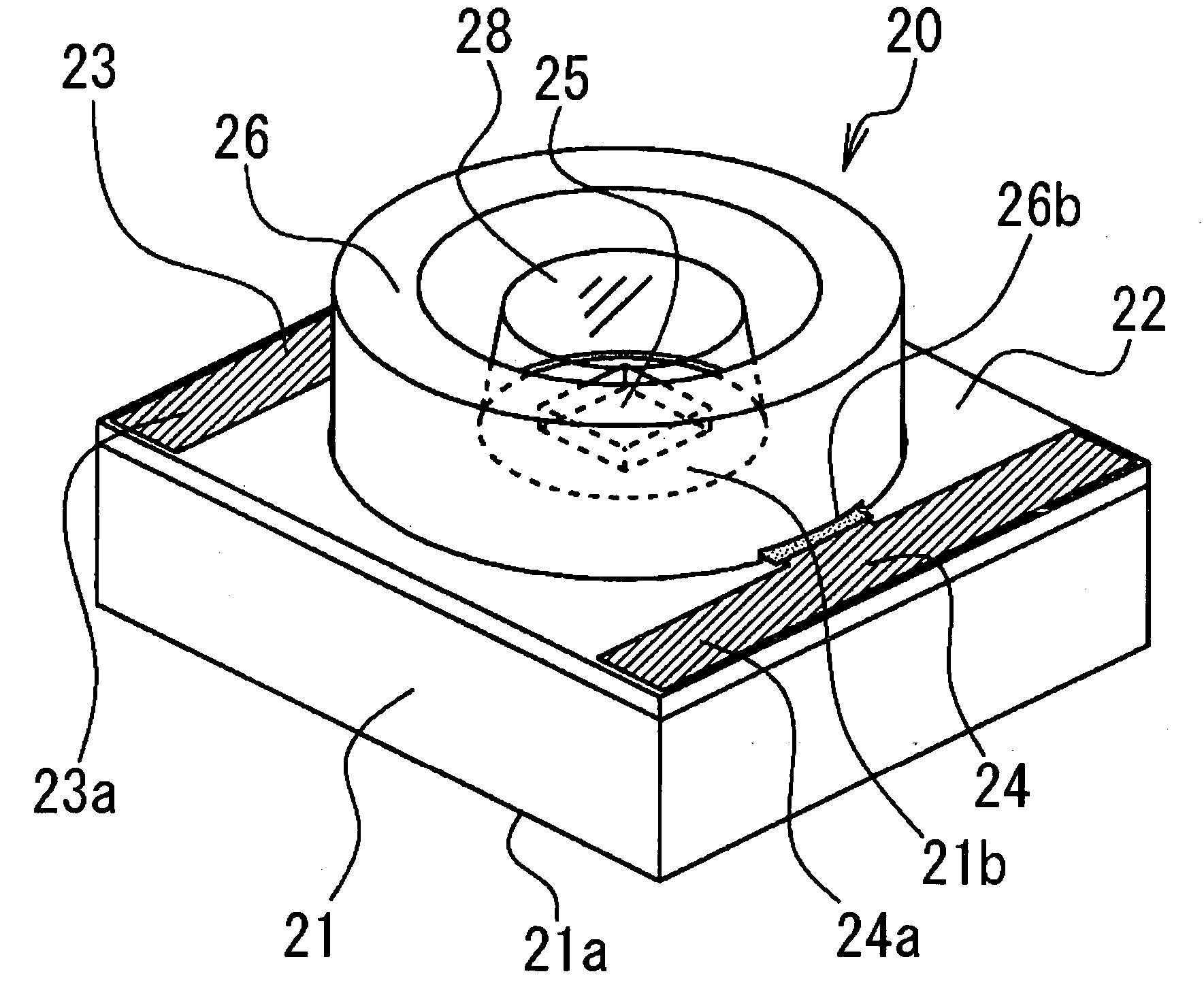
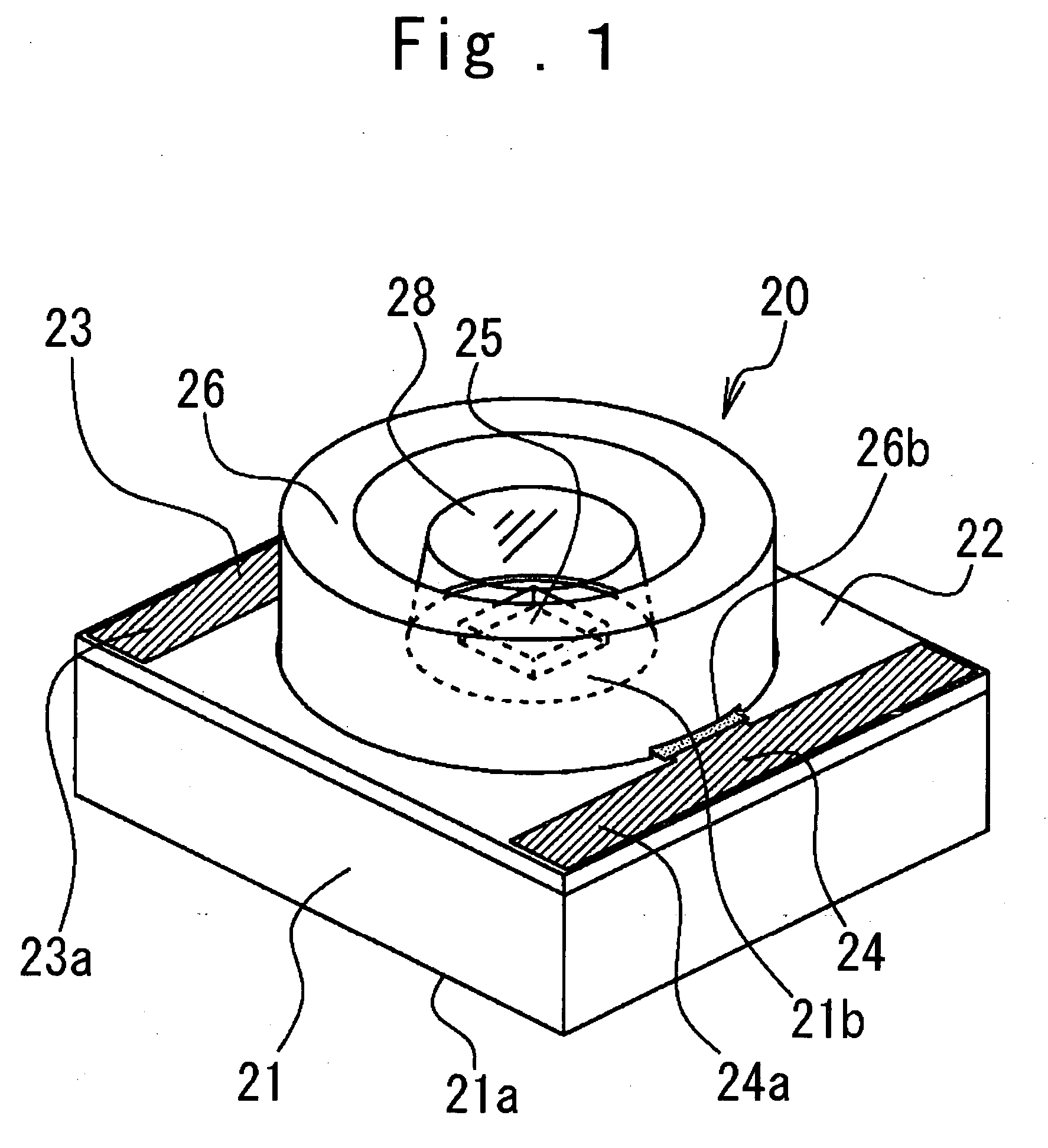
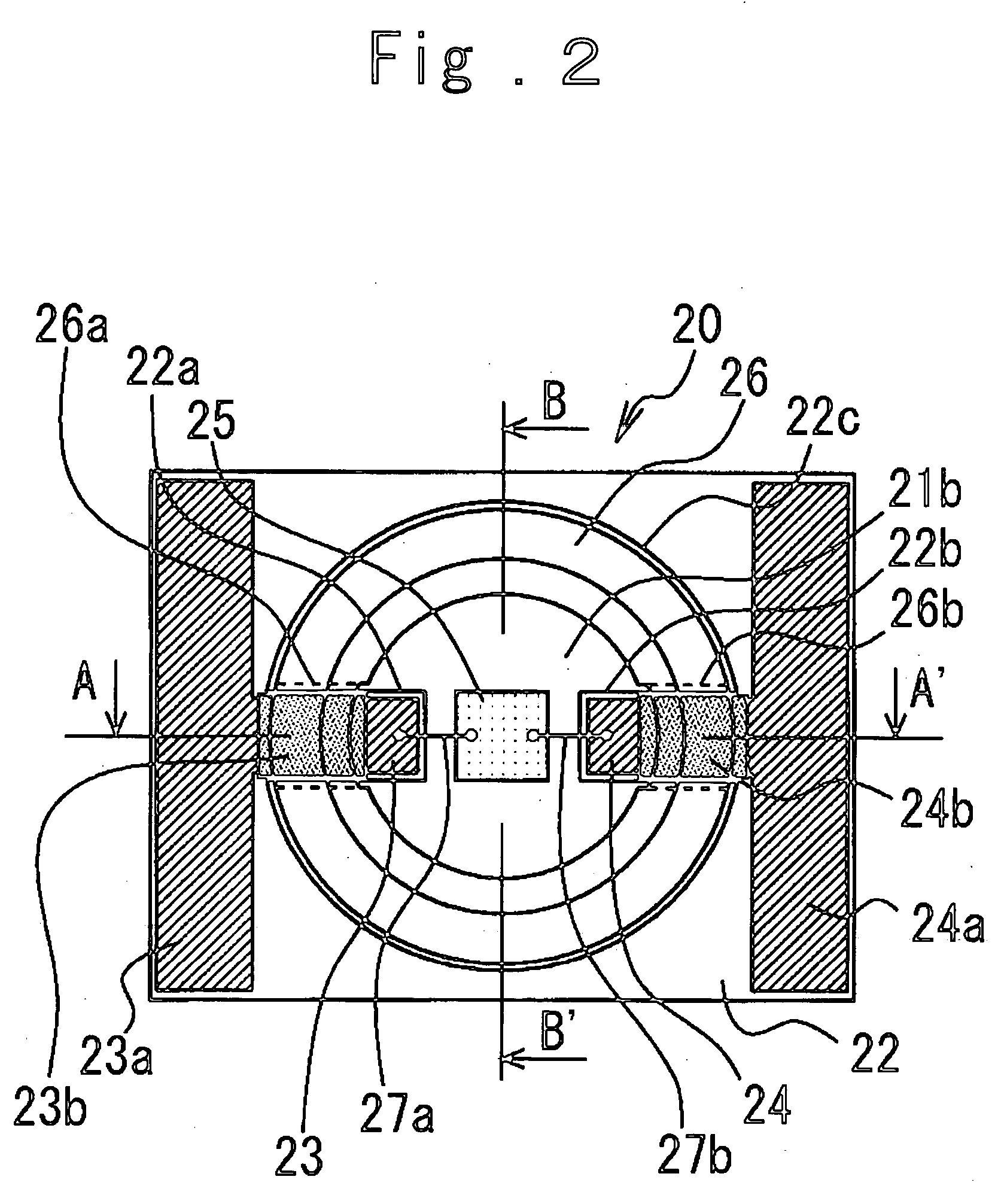
[0040] Next, the structure of the surface-mounted LED in the present invention will be described in more detail referring to FIGS. 3 and 4.
[0041] In FIG. 3, the wiring board protrusions 22a and 22b extend from the vicinity of opposite end portions of the wiring board 22 passing through the lower portion of the reflective frame 26 to the vicinity of the center of the base 21 and are close to the LED chip 25.
[0042] The conductive patterns 23 and 24 on the wiring board protrusions 22a, 22b are also close to the LED chip 25 passing through the lower portion of the reflective frame 26. Meanwhile, because the reflective frame 26 avoids the wiring board protrusions 22a, 22b and the conductive patterns 23, 24 by the reflective frame concave portions 26a, 26b, the disposition of the wiring board protrusions 22a, 22b and the conductive patterns 23, 24 is not blocked by the reflective frame 26.
[0043] The anode and cathode terminals (not shown) of the LED chip 25 are electrically connected wi...
second embodiment
[0051] Next, the present invention will be explained referring to FIGS. 5 and 6.
[0052] In the drawings, the same numerals are attached to the similar parts as in the first embodiment in FIG. 1 and the overlapped description is omitted.
[0053] In FIGS. 5 and 6, 30 is a surface-mounted LED in the second embodiment of the present invention.
[0054] The wiring board 22 is disposed to run around the heat releasing part 21a on the lower surface of the base 21 from both end surfaces 21c and 21d of the base 21. The conductive patterns 23 and 24 formed on the wiring board 22 are also disposed to run around the wiring board 22 and therefore terminal portions 23b and 24b as electrical connection surfaces are formed on the lower surface of the base 21. As a result, the terminal portions 23b and 24b are connected electrically and mechanically with the outside printed-circuit board by the surface-mounting, as described hereinafter, to enable a driving current to supply to the LED chip 25 by means ...
third embodiment
[0056] Subsequently, the present invention will be explained referring to FIG. 7.
[0057] In FIG. 7, the same numerals are attached to the similar parts as in the first embodiment of the present invention and the overlapped description is partially omitted.
[0058] In FIG. 7, 40 is a light emitting device according to the present invention, which is composed of the surface-mounted LED 20, a printed-circuit board 41 as a substrate and two heat release members 42 and 43 each made of a material having heat conductivity.
[0059] The printed-circuit board 41 has conductive patterns 41a each comprising a copper foil or the like and a mounting hole 41b which is generally circular. Here, the surface-mounted LED 20 is disposed to be fitted in the mounting hole 41b of the printed-circuit board 41, and the terminal portions 23a and 24a of the surface-mounted LED 20 and the conductive patterns 41a of the printed-circuit board 41 are electrically and mechanically connected by soldering 45 as connect...
PUM
 Abstract
Description
Claims
Application Information
 - R&D
- Intellectual Property
- Life Sciences
- Materials
- Tech Scout
- Unparalleled Data Quality
- Higher Quality Content
- 60% Fewer Hallucinations
Browse by: Latest US Patents, China's latest patents, Technical Efficacy Thesaurus, Application Domain, Technology Topic, Popular Technical Reports.
© 2025 PatSnap. All rights reserved.Legal|Privacy policy|Modern Slavery Act Transparency Statement|Sitemap|About US| Contact US: help@patsnap.com


