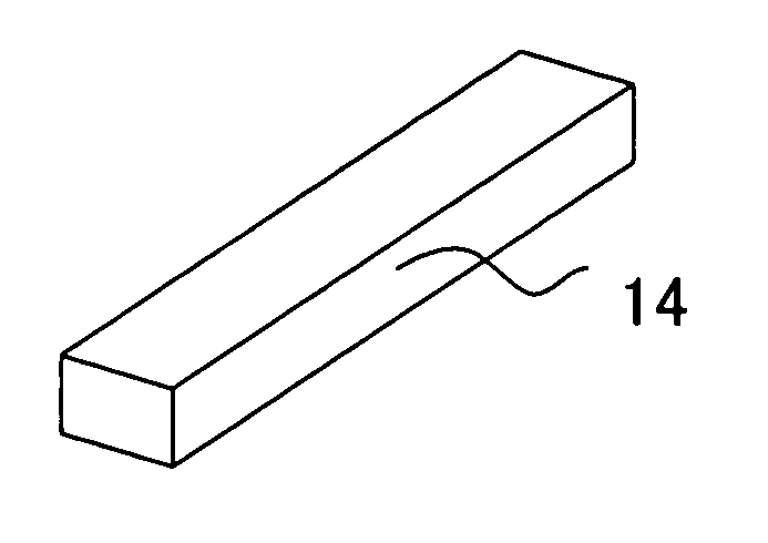
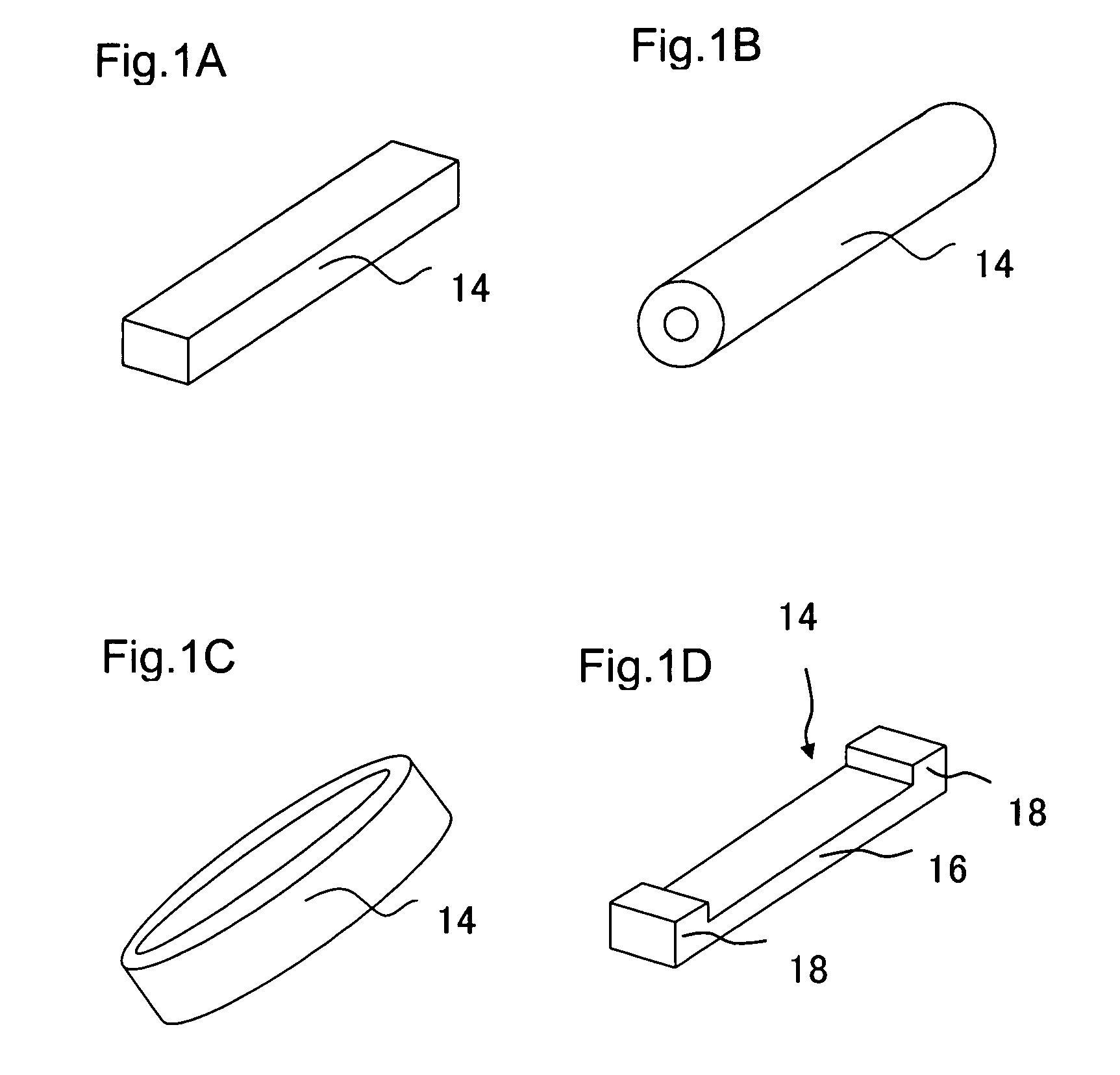
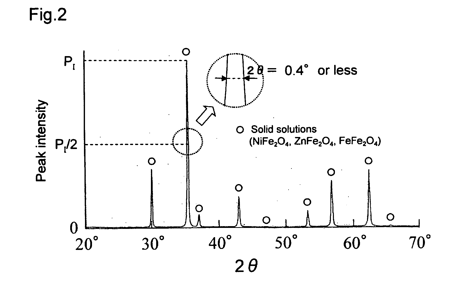
However, it is difficult to measure the air pressure or temperature in the tire by using the sintered ferrite disclosed in Patent Documents 1 to 6 as the ferrite or magnetic material used in the RFID technology disclosed in Patent Documents 7 to 13.
This is because a sufficient level of induced
electromotive force cannot be generated in the ferrite coil that uses the sintered ferrite disclosed in Patent Documents 1 to 6, and therefore a sufficient
signal directing the
pressure sensor or the temperature sensor to measure the pressure or temperature in the tire is not transmitted to a
pressure sensor or a temperature sensor.
When the sintered ferrite disclosed in Patent Documents 1 to 6 is used to make the ferrite coil of the
loop antenna apparatus of
Patent Document 13, it is difficult to lock and unlock the vehicle door.
Difficulty in measuring the air pressure or temperature in the tire or in locking and unlocking the door is caused because sufficient induced
electromotive force is not generated in the ferrite coil made of the sintered ferrite of Patent Documents 1 to 6.
But the conventional sintered ferrite materials do not satisfy these requirements.
A ferrite coil made of the sintered ferrite of Patent Documents 1 to 6 may have low sensitivity per one winding that is determined by dividing the induced
electromotive force, generated in the ferrite coil when a
magnetic field is applied thereto, by the intensity of the applied
magnetic field, thus giving rise to such a problem that the sintered ferrite core used for the ferrite coil must be made larger and the number of windings must be increased, resulting in difficulty to make the ferrite coil smaller.
There has also been such a problem that making the ferrite coil smaller leads to lower level of induced electromotive force.
Crystalline structure of the ferrite core made of the conventional sintered ferrite is sometimes poorly ordered, thus resulting in
large core loss, low magnetic permeability and low
Curie temperature.
In such a case, the ferrite core for RFID application that uses the ferrite core made of the conventional sintered ferrite has insufficient level of induced electromotive force.
However, with the conventional sintered ferrite that has such trouble as the crystalline structure is poorly ordered and / or the
crystal grain size is not controlled, it has not been possible to achieve sufficiently high
mechanical strength on stable basis.
Moreover, since tires may be exposed to intense mechanical vibrations at high temperatures, the sintered ferrite that constitutes the ferrite core for RFID application is required to have not only low core loss, high
Curie temperature and high magnetic permeability, but also small relative
temperature coefficient of magnetic permeability in absolute value and highly dense structure, depending on the application.
The sintered ferrite that constitutes the ferrite core disclosed in the prior art cannot satisfy these requirements.
Further, since there is no description about carefully crushing the calcined material, unsatisfactory characteristics sometimes result such as
large core loss, low magnetic permeability, low
Curie temperature and / or low
mechanical strength, in case the particle sizes of the calcined
powder are larger which leads to insufficiently ordered crystalline structure of the sintered body.
Patent Document 2 specifies the crystal grain size distribution of the ferrite material, but a
large core loss sometimes results because the particle sizes of the
powder are larger before
calcination which leads to larger size of crushed
powder after
calcination and to crystalline structure that is not ordered.
As a result, the crystalline structure of the sintered body is not sufficiently ordered, thus resulting in large core loss, low magnetic permeability, low
Curie temperature and / or low
mechanical strength.
However, larger core loss sometimes results due to the following causes.
In case particle sizes of the powder before
calcination are large in the process of manufacturing the sintered ferrite, it may become impossible to sufficiently synthesize the calcined powder, namely a powder that has
spinel structure and consists of crystal grains having sufficiently ordered crystalline structure.
Cause of insufficient synthesis is that powders of Fe2O3, NiO, ZnO and CuO do not react sufficiently in the calcination process, thus resulting in insufficient growth of the crystal grains of
spinel structure, and therefore much of the powders of Fe2O3, NiO, ZnO and CuO remain in the state of calcined powder without reacting.
When the calcined powder containing much non-reacted powder is sintered, crystalline structure of the crystal phase having
spinel structure cannot be ordered enough during the
sintering process.
Therefore, when particle sizes of the powder before calcination are large, much crystal of which structure is not sufficiently ordered remains in the sintered body, thus resulting in large core loss.
Even when the calcined powder is synthesized sufficiently, insufficient crushing of the calcined powder results in large particles contained in the powder before calcination, and therefore crystalline structure of the sintered body is not sufficiently ordered and core loss becomes larger.
The greater the variations in the composition, the more the
lattice defects generated in the crystal of spinel structure, resulting in irregular crystalline structure.
This is because insufficient crushing of calcined powder causes the composition of the crystal grains contained in the sintered body to vary, and
sintering of the material having the varying compositions not corrected leads to variations in the composition of the crystal grains contained in the sintered body, thus resulting in the sintered body having crystalline structure that is not ordered enough.
As described above, since the sintered ferrite or the ferrite material of Patent Documents 1 to 6 does not have low core loss, high magnetic permeability and / or high
Curie temperature, the ferrite coil made from such sintered ferrite or the ferrite material has a problem of low induced electromotive force generated by each winding when subjected to a
magnetic field.
Thus it is difficult to apply the ferrite coil made from the sintered ferrite or the ferrite material of Patent Documents 1 to 6 to ferrite core for RFID application that is required to have large induced electromotive force, high sensitivity and good mechanical properties.


