Direct fuel-injected internal combustion engine having improved spark ignition system

Inactive Publication Date: 2005-03-24
BRP US
View PDF13 Cites 9 Cited by
  • Summary
  • Abstract
  • Description
  • Claims
  • Application Information

AI Technical Summary

Benefits of technology

[0008] The present invention is directed to a direct fuel injection outboard marine engine having an improved spark ignition system. This spark ignition system comprises a magnetic core-coil assembly for generating a high-voltage signal within a short period of time and an electronic engine management module for energizing a primary coil of the magnetic core-coil assembly with a low-voltage signal at the appropriate time. The magnetic core is made of ferromagnetic amorphous metal alloy which exhibits low core loss and a permeability in the range of 100 to 500. Such magnetic properties are well suited for rapid firing of a spark plug during each piston stroke.
[0010] The magnetic amorphous metal core-coil assembly in accordance with the preferred embodiment minimizes the number of engine misfires due to soot fouling. The resulting coil-per-plug spark ignition transformer generates a rapid voltage rise and a signal that accurately portrays the voltage profile of the ignition event. Energy transfer from the amorphous metal coil to the spark plug occurs in a very efficient manner, so that very little energy remains within the core after discharge. The low secondary resistance of the toroidal design allows the bulk of the energy to be dissipated in the spark and not in the secondary wire.

Problems solved by technology

Tardy spark ignition leads to loss of engine power and loss of efficiency, while early spark ignition leads to detonation, often called “ping” or “knock”, which can, in turn, lead to detrimental pre-ignition and subsequent engine damage.
In addition, extended part throttle operation and cold starts can lead to the deposition of electrically conductive soot on the spark plug insulator which reduces the voltage increase available for generating a spark.

Method used


Image

  • Direct fuel-injected internal combustion engine having improved spark ignition system
  • Direct fuel-injected internal combustion engine having improved spark ignition system
  • Direct fuel-injected internal combustion engine having improved spark ignition system

Examples


Embodiment Construction

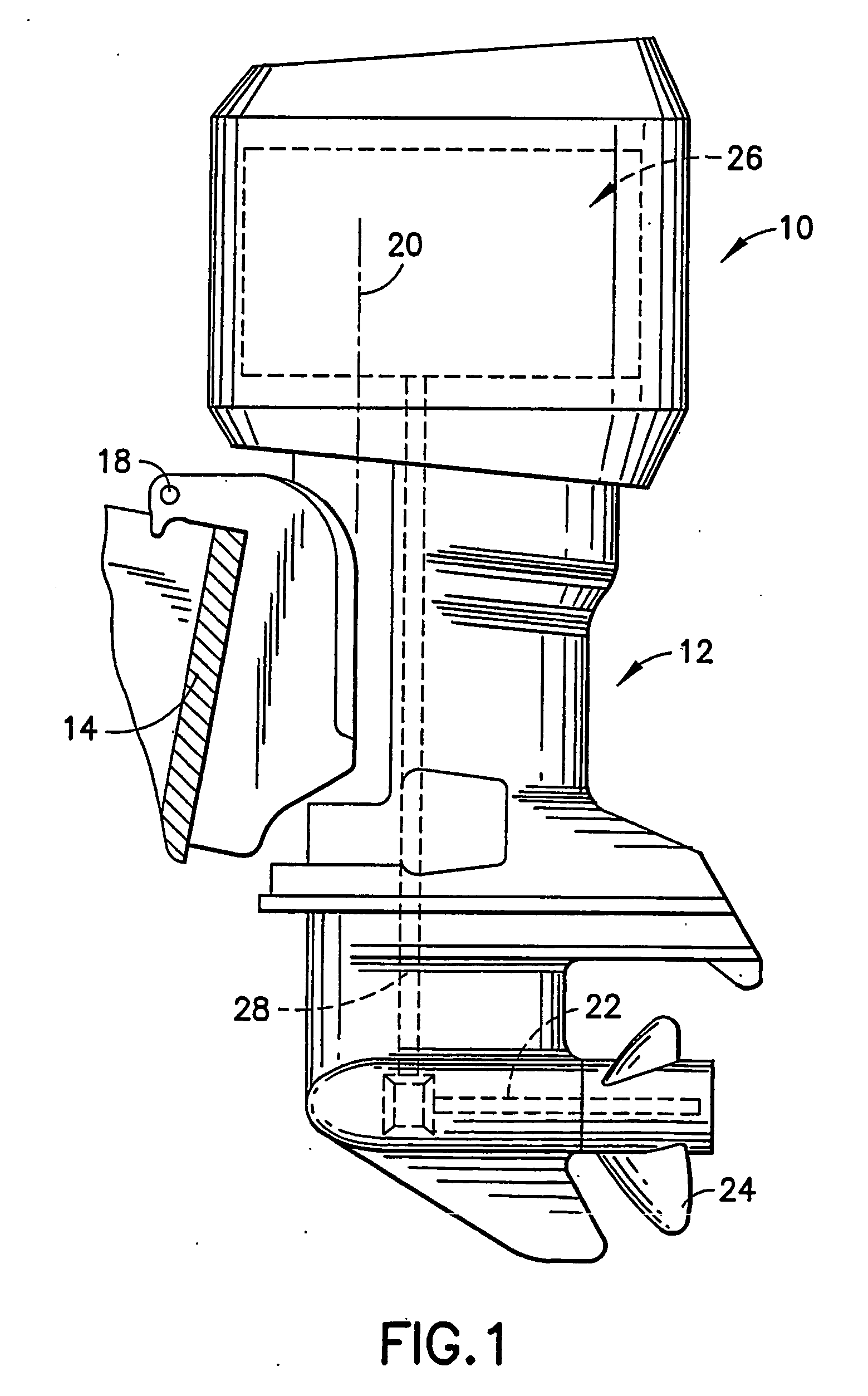
[0016] The present invention will be described in the context of an outboard marine propulsion device powered by a two-stroke direct fuel injection internal combustion engine for driving a propeller. However, it will be appreciated by those skilled in the art that the teachings of the present invention need not be limited to outboard systems or to two-stroke engine operation or to propeller systems since other applications, such as inboard engines, four-stroke engine operation and water jet propulsion units, may equally benefit from such teachings. An exemplary outboard marine propulsion device incorporating the invention is illustrated in FIG. 1.

[0017] The marine propulsion device 10 shown in FIG. 1 comprises an outboard drive unit 12 adapted to be mounted to a transom 14 of a boat for pivotal tilting movement relative thereto about a generally horizontal tilt axis 18 and for pivotal steering movement relative thereto about a generally vertical steering axis 20. Drive unit 12 comp...


PUM


Abstract

A direct fuel injection outboard marine engine having an improved spark ignition system. This spark ignition system includes a magnetic core-coil assembly for generating a high-voltage signal within a short period of time and an electronic engine management module for energizing a primary coil of the magnetic core-coil assembly with a low-voltage signal at the appropriate time. The magnetic core is made of ferromagnetic amorphous metal alloy which exhibits low core loss and a permeability in the range of 100 to 500. The high-voltage signal is output by a secondary coil wound around a major portion of the core, with the primary coil being wound around a minor portion of the core. The secondary coil outputs a high-voltage signal to a spark plug in response to excitation of the primary coil with a low-voltage signal generated by the electronic engine management module.

Description

FIELD OF THE INVENTION [0001] This invention generally relates to direct fuel-injected internal combustion engines, such as two-stroke or four-stroke engines. In particular, the invention relates to marine propulsion systems which include such engines. BACKGROUND OF THE INVENTION [0002] The most common internal combustion engines are classified as either two-stroke cycle or four-stroke cycle. The majority of outboard marine engines use two-stroke technology, but there are also outboard marine engines that use four-stroke technology. The engine technologies used in outboard marine engines are selected based on the power, performance and efficiency needs of the specific engine family. [0003] Direct fuel injection is a process of injecting fuel charge directly into the combustion chamber. Modern direct fuel injection technology uses an electronic engine management system to coordinate delivery of precise fuel quantities into the combustion chamber. [0004] One known injection method bla...

Claims


Application Information

Patent Timeline
IPC IPC(8): F02B1/04F02B61/04F02B75/02F02B75/12F02D37/02F02P3/02H01F30/16H01F38/12
CPCF02B1/04F02B61/045F02B2075/025F02B2075/125F02D37/02Y02T10/123F02D2400/04F02P3/02H01F30/16H01F38/12Y02T10/12F02D2041/389
Inventor BRIDGE, MATTHEW L
Owner BRP US
Why Eureka
Try Eureka