
Portable plastic pipe cutter beveller system

Inactive Publication Date: 2005-02-03
VIOLA DANIEL +2
View PDF18 Cites 27 Cited by
  • Summary
  • Abstract
  • Description
  • Claims
  • Application Information

AI Technical Summary

Problems solved by technology

Traditionally, when the pipe sections are cut in the field, it is not generally convenient to utilize electrical power which may not be available.
In many cases, any portable gas saws utilize carbide blades which are relatively difficult to utilize and accordingly the ends of the cut plastic pipes are not accurate and tend to wander.
Furthermore, the user of the portable gasoline engine saws must hold the saw steady so as to prevent any potential kickback, which can be a serious safety hazard.
These and other prior devices are relatively complicated and difficult to use.

Method used


Image

  • Portable plastic pipe cutter beveller system
  • Portable plastic pipe cutter beveller system
  • Portable plastic pipe cutter beveller system

Examples


Embodiment Construction

[0023] Like parts have like numbers throughout the figures.

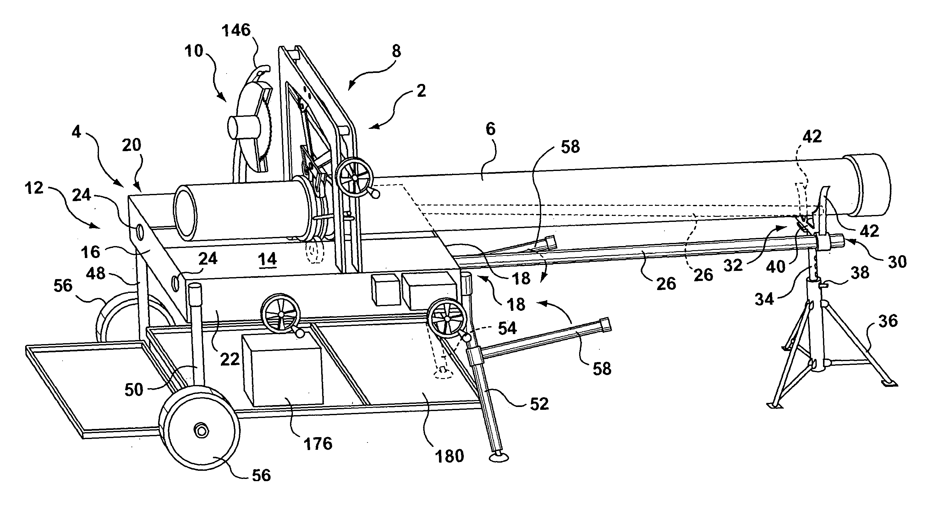
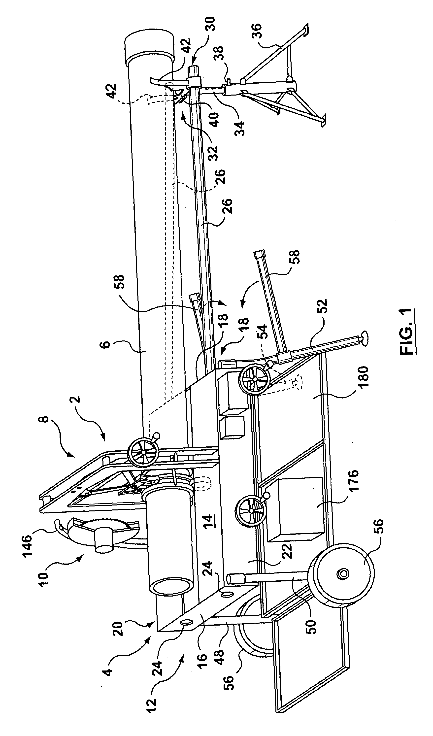
[0024]FIG. 1 illustrates the pipe-cutting device 2 which includes a support 4 for supporting the pipe 6, means 8 for rotating the pipe 6 relative to the support 4 and a cutter 10 associated with the support 4 for cutting the pipe 6 during rotation of the pipe 6.

[0025] In particular, the support 4 consists of a table 12 which has a top 14 ends 16 and 18 and sides 20 and 22. The ends 16 and 18 include a pair of guide holes 24, each of which are adapted to receive guide extensions 26 which are disposed generally horizontally as best seen in FIG. 1. More specifically, one end 28 of each of the guide extensions 26 are adapted to be received by the guide holes 24, while another end 30 are adapted to rest on a self-leveling pad 32 as best seen in FIG. 1 and FIG. 8.

[0026] The self-leveling pad 32 includes a vertical extension 34 which can be adjusted in height by telescopingly moving the extension 34 relative to the pad legs. 36 ...


PUM

PropertyMeasurementUnit
Pressureaaaaaaaaaa
Speedaaaaaaaaaa

Abstract

A pipe-cutting device comprising a portable support; means for rotating said pipe relative said support; a cutter associated with said support for cutting said pipe during rotation of said pipe.

Description

FIELD OF INVENTION [0001] This invention relates to a pipe-cutting device, and particularly relates to a portable device for cutting plastic pipes and beveling the ends thereof in the field. The invention also relates to a method of cutting and beveling plastic pipes in the field. BACKGROUND TO THE INVENTION [0002] Various pipes are required to be installed including pipes disposed below ground. Invariably, some of the pipe sections need to be cut to size before joining abutting ends. Such pipes can comprise of a variety of materials, including metal, steel, copper, plastic or the like. Various underground water and sewer pipes are comprised of PVC pipe which also need to be cut in the field. [0003] Traditionally, when the pipe sections are cut in the field, it is not generally convenient to utilize electrical power which may not be available. Accordingly, it is not uncommon that portable saws which are powered by gasoline engines are utilized. In many cases, any portable gas saws u...

Claims


Application Information

Patent Timeline
IPC IPC(8): B23B31/20B23C3/12B23D45/12
CPCB23B31/202B23C3/122B23D45/124Y10T29/49789Y10T29/5148Y10T82/22Y10T29/49996Y10T82/16967Y10T29/5114Y10T29/5199Y10T83/0596
Inventor VIOLA, DANIELDODGSON, RANDYDE SYLVA, DAVID
Owner VIOLA DANIEL
Learn More