Eureka AIR delivers breakthrough ideas for toughest innovation challenges, trusted by R&D personnel around the world.

Optical compensatory sheet producing method and apparatus, thermal treating method and apparatus, and dust removing method and apparatus

Inactive Publication Date: 2005-01-27
FUJIFILM HLDG CORP
View PDF14 Cites 13 Cited by
  • Summary
  • Abstract
  • Description
  • Claims
  • Application Information

AI Technical Summary

Benefits of technology

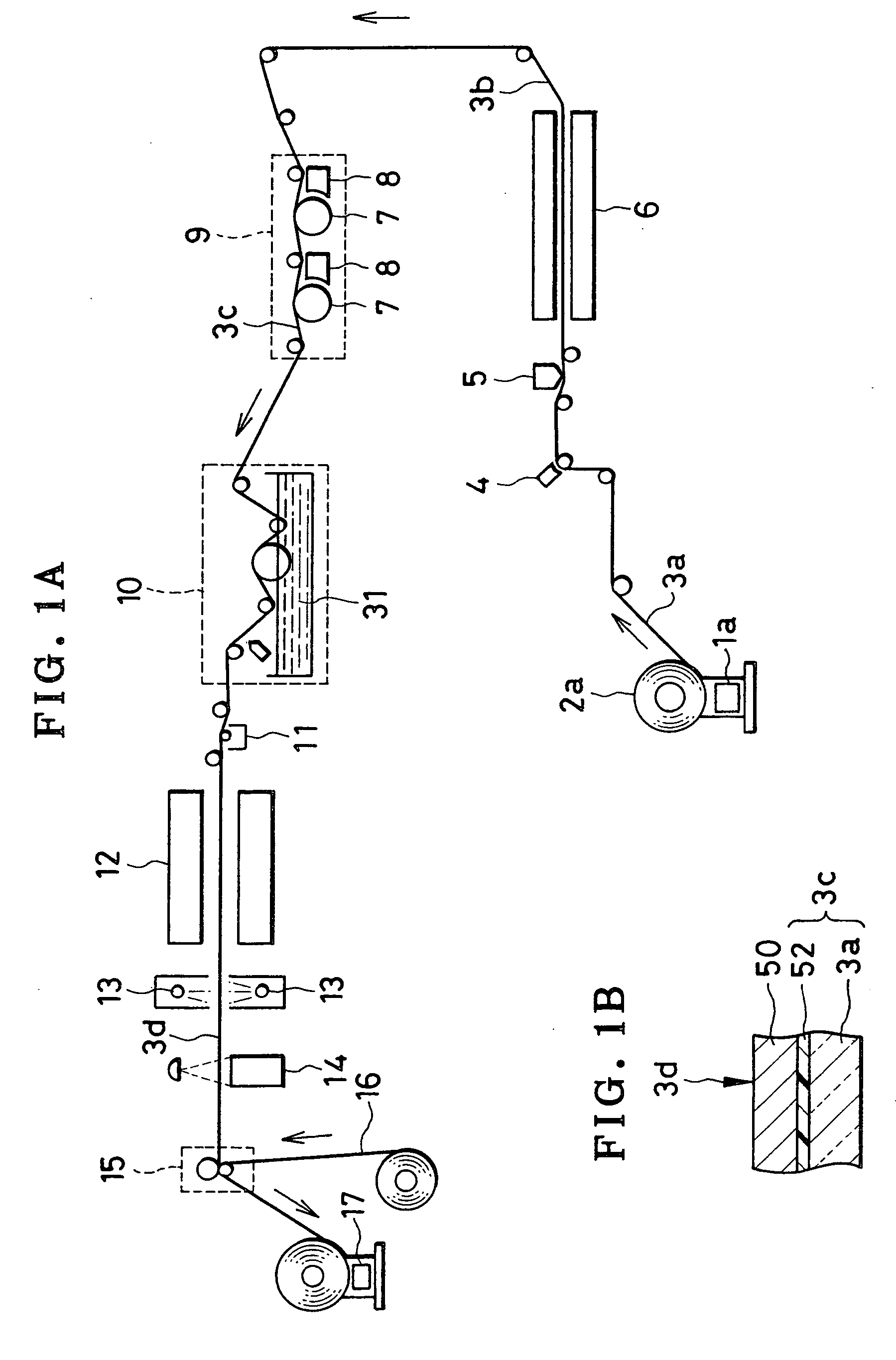
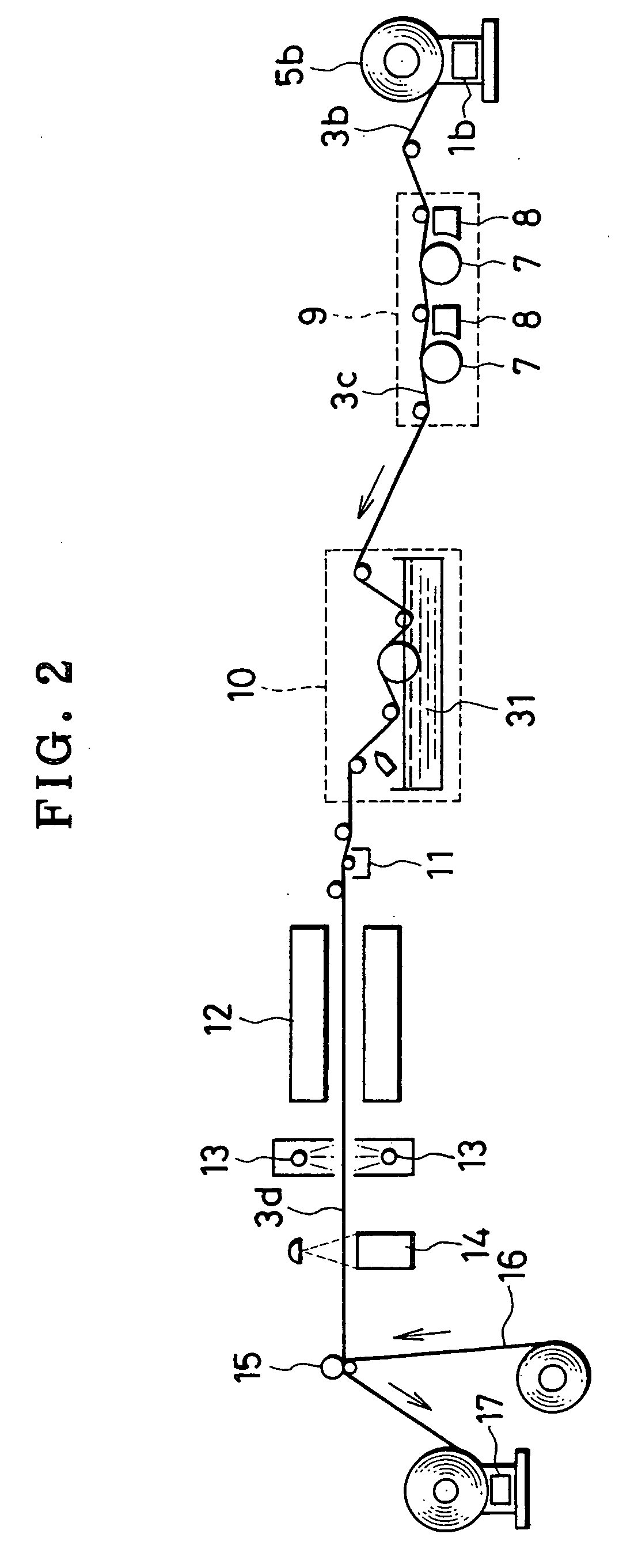
[0024] In view of the foregoing problems, an object of the present invention is to provide an optical compensatory sheet producing method and apparatus in which an optical compensatory sheet can be easily and efficiently obtained with high quality for good contrast and color in a liquid crystal display unit.
[0025] Another object of the present invention is to provide a thermal treating method and apparatus in which sheet material can be heated without irregularity.
[0026] Still another object of the present invention is to provide a dust removing method and apparatus capable of removing dust from sheet material without scratching or damaging its surface.
[0035] Consequently, an optical compensatory sheet can be easily and efficiently obtained with high quality for good contrast and color in a liquid crystal display unit, because the dust remover removes dust from the orientation layer by use of liquid to which the orientation layer is insoluble, and because the orientation layer is polished with the liquid in a direction equal to a direction of the rubbing process.
[0050] Consequently, web can be heated without irregularity, because the exhaust unit is disposed upstream or downstream from the hot air supply unit in a traveling direction of the web.
[0065] Consequently, it is possible to remove dust from sheet material without scratching or damaging its surface, because the cleaning member and pinch member nip the web, and the cleaning member polishes the first surface with liquid.

Problems solved by technology

However, the STN-LCD has disadvantages in providing good contrast only when set in the yellow mode (yellowish green / deep blue) or blue mode (blue / pale yellow).
However, TN-LCD has disadvantages that color or contrast on display varies with changes in viewing angle to LCD, and its display characteristics are not comparable to display characteristics of CRT.
To prepare the above sheet by the stretching treatment, extremely complicated treatments are required.
Therefore, an optical compensatory sheet of a large surface are cannot be easily produced according to the disclosed process.
However, polymers having a liquid crystalline property have a shortcoming in low productivity and are unsuitable for mass production, because it needs orientation by ripening for a long time at high temperature.
This creates dust such as minute particles of resin.
When LCD is provided with the optical compensatory sheet, the defects occur in a display state.
However, there is a problem in that occurrence of the defects gradually becomes frequent according to dust.
Furthermore, renewal of the rubbing sheet must be periodical, and inconsistent to continuous operation of the manufacture.
There are problems in that yield of products of the optical compensatory sheet decreases to increase the manufacturing cost, and that efficiency in manufacturing operation becomes lower according to inspection of the offsetting of the orientation axis and the discarding operation.
However, it is experimentally found that the known cleaning methods are nearly ineffective to dust of particles of 10 μm or less, or dust stuck with strong adhesion.
However, problems arise in the method of JP-B 5-050419 (corresponding to JP-A 62-060749) and JP-A 62-065872.
Damages or scratches may occur in the resin film if hard foreign matter or dust becomes squeezed between the cleaning rod and the resin film.

Method used


Image

  • Optical compensatory sheet producing method and apparatus, thermal treating method and apparatus, and dust removing method and apparatus
  • Optical compensatory sheet producing method and apparatus, thermal treating method and apparatus, and dust removing method and apparatus
  • Optical compensatory sheet producing method and apparatus, thermal treating method and apparatus, and dust removing method and apparatus

Examples


examples

[0272] Comparative Example 6 (Prior Art)

[0273] In FIG. 16, a web supply device 201 supplied polyethylene terephthalate film at a speed of 50 m / min. The film was 100 μm thick and 100 cm wide. A coater head 202 coated the film with coating solution including particles of latex of which average diameters were 3 μm and 10 μm. A drier zone 203 evaporated the coating solution to obtain film in which an amount of deposited foreign matter was controlled. Composition of the coating solution including the latex was as follows:

3 μm latex stock solution0.1 ml10 μm latex stock solution3.0 mlMethanol46.9 ml Pure water50.0 ml 

[0274] The latex stock solution includes monodisperse polystyrene latex at 1 wt. %. The resin film 210 was coated with the solution at 25 ml / m2. A surface of the resin film 210 was dried, and then checked visually through a microscope. It was observed that latex particles of 3 μm and 10 μm were regularly deposited on the surface at a density of approximately 1,000 particle...


PUM


Abstract

An optical compensatory sheet producing apparatus produces an optical compensatory sheet having a liquid crystal layer. In the apparatus, a rubbing unit is supplied with resin film having a first layer including resin, and subjects the first layer to a rubbing process, so as to form an orientation layer. A dust remover removes dust from the orientation layer by use of liquid such as perfluorocarbon, to which the orientation layer is insoluble. A liquid crystal layer coater is disposed downstream from the dust remover, for coating the orientation layer with coating liquid including liquid crystalline compound, so that the liquid crystal layer is formed.

Description

BACKGROUND OF THE INVENTION [0001] 1. Field of the Invention [0002] The present invention relates to an optical compensatory sheet producing method and apparatus, thermal treating method and apparatus, and dust removing method and apparatus. More particularly, the present invention relates to an optical compensatory sheet producing method and apparatus in which an optical compensatory sheet can be obtained with high quality for good contrast and color in a liquid crystal display unit, and thermal treating method and apparatus, and dust removing method and apparatus for the optical compensatory sheet. [0003] 2. Description Related to the Prior Art [0004] A liquid crystal display unit (LCD) is characterized in having a shape with a small thickness, being lightweight and using low electric power in comparison with a cathode ray tube (CRT) to display an image. LCD is used widely as a component incorporated in a portable type of word processor and a desk-top type of personal computer. In...

Claims


Application Information

Patent Timeline
IPC IPC(8): G02B5/30G02F1/13363
CPCB05D3/0413B05D7/04G02F2001/133633G02B5/3083G02F1/13363G02B5/3016G02F1/133633B05D3/0254G02F1/133784
Inventor ISHIZUKA, SEIJIURA, MUNEHIROSUGIYAMA, TADASHINAKAJIMA, KENJIFUJIWARA, KAZUHIKOKAWANISHI, NAOYUKI
Owner FUJIFILM HLDG CORP
Why Eureka
Eureka Blog
Learn More