
Support for a vehicle jack

a vehicle jack and support technology, applied in the direction of inclined ship lifting, lifting devices, ship-lifting devices, etc., can solve the problems of vehicle jacks, especially, being susceptible to lateral/horizontal and/or vertical movement, and exacerbated problems, so as to improve the stability and/or safety of vehicle jack use.

Inactive Publication Date: 2005-01-27
LUCAS BRETT LEWIS
View PDF11 Cites 19 Cited by
  • Summary
  • Abstract
  • Description
  • Claims
  • Application Information

AI Technical Summary

Benefits of technology

[0008] It is therefore an object of the invention to alleviate to some extent, one or more of the aforementioned problems and preferably to improve the stability and / or safety of vehicle jack use, and especially, but not limited to, use of the manufacturers supplied vehicle jack.
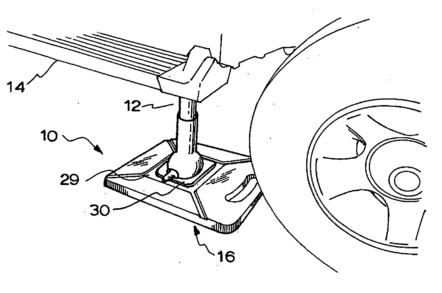
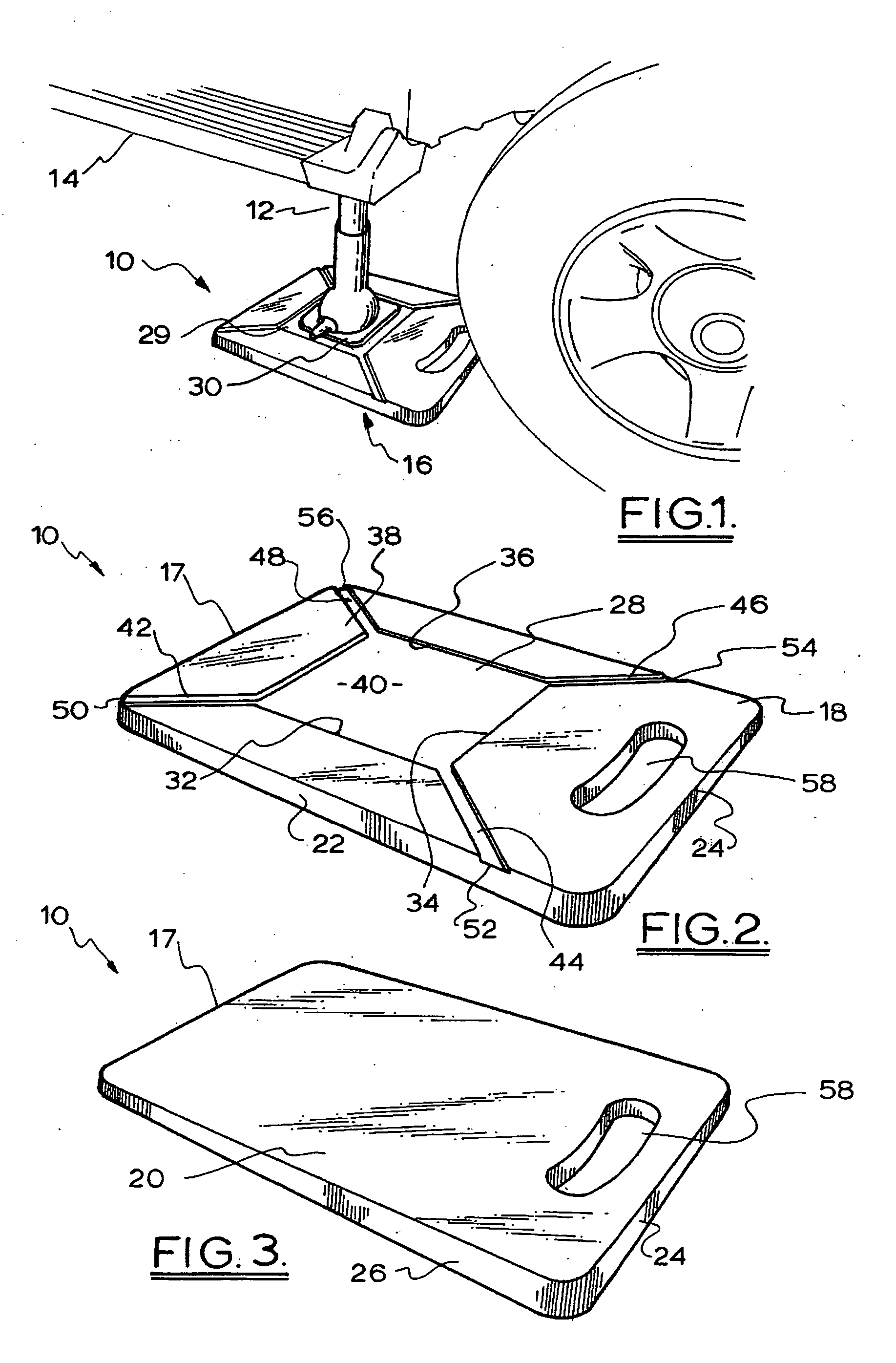
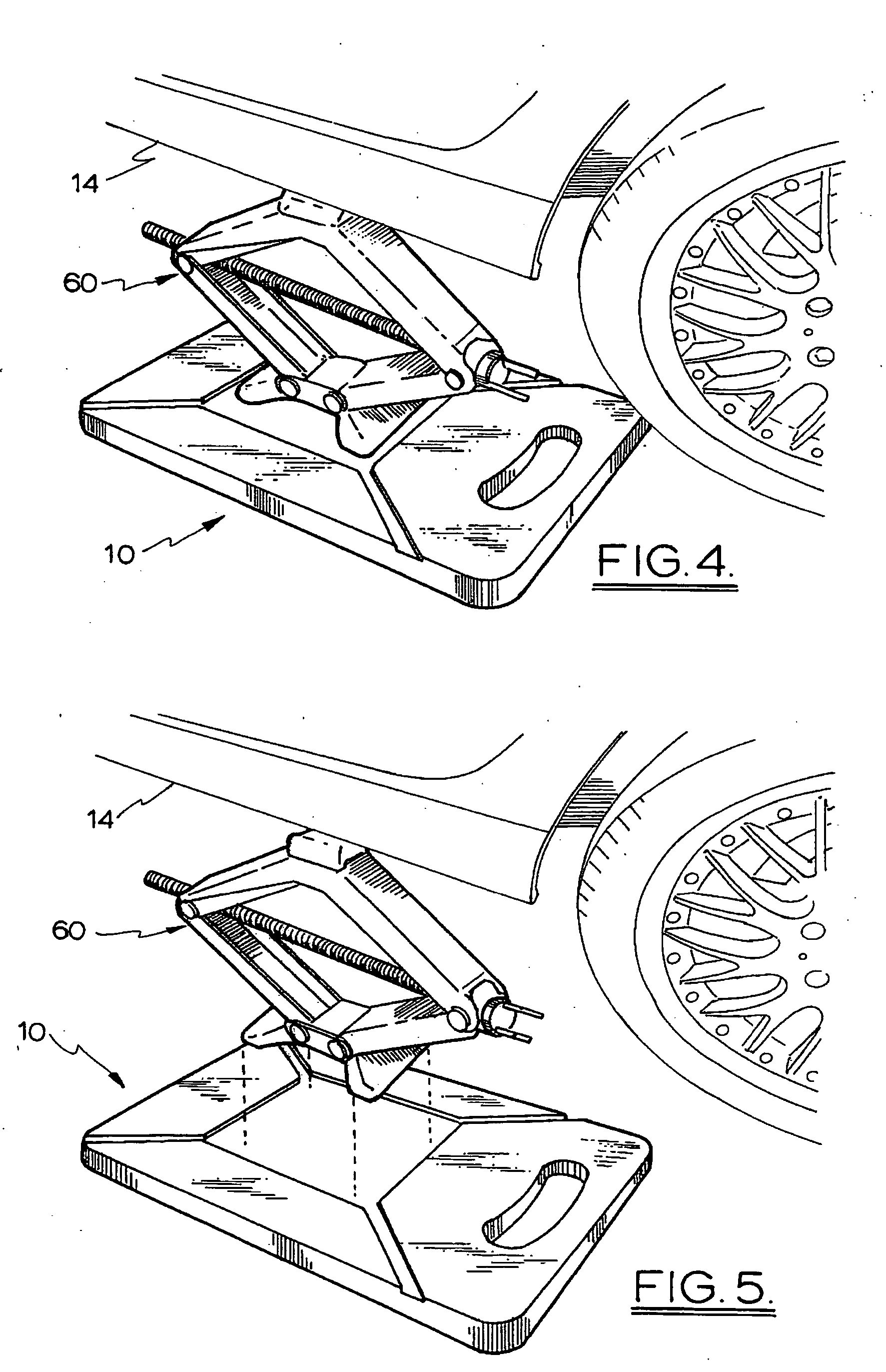
[0017] Preferably, the recess comprises a base and at least one side wall connected to the base, the slippage obstruction means comprising the or each side wall of the recess. Preferably, the base of the recess includes a slip resistive surface, on which lateral movement of the seated base portion of the vehicle jack is resisted, such as a concentrically corrugated or a checked surface. Preferably, the recess is generally centrally located in the upper surface of the support for substantially even load distribution. In a preferred form, the recess is generally centrally located but offset from a marginal edge of the support body which includes a holding means. Preferably, the recess has a depth sized relative to the support body to resist deformation of the support body during use whilst nonetheless being of sufficient depth to obstruct slippage of the base portion of the vehicle jack. Preferably, the depth of the recess is shallow. In one form it is preferred that the recess be dimensioned for non-tight fitting reversible insertion and seating of the base portion of the vehicle jack therein in position on the support. More preferably, there is a small lateral clearance between the recess side wall(s) and the base portion of the positioned vehicle jack which facilitates simple use of the support with potentially a range of different vehicle jack base portion configurations and sizes (including, but not limited to manufacturers supplied vehicle jacks, high lift jacks, etc.) whilst facilitating at most only limited slippage of the jack base portion therein.
[0018] In an alternative form, it is preferred that the recess be dimensioned for tight fitting reversible insertion and seating of the base portion of the vehicle jack in the recess in position on the support. More preferably, the recess has a configuration corresponding to the base portion of the vehicle jack, being custom made for optimal use and limitation of slippage of a particularly configured and sized vehicle jack base portion.
[0020] Preferably, the support further includes holding means for use in the carriage, storage, and most preferably the positioning for use and / or removal from a position of use of the support. Preferably, the holding means comprises a finger grip or a handle. Preferably, the holding means is positioned at a marginal edge of the support body and more preferably medially at the marginal edge. Preferably, the holding means comprises an integral handle defined by an aperture in the support body. It is particularly preferred that the handle be so formed, dimensioned and arranged that it may aide positioning of the support using a steering action to steer the support into operative position. Preferably, the holding means is generally rigid.
[0024] Preferably, the support body has a surface area sized proportionally larger than a surface area of the base portion of a vehicle jack so as to distribute the force of the load (i.e. the supported weight of the vehicle jack raising at least part of a vehicle in use) from said base portion to a larger surface area of ground surface on which the support is rested for improved jack stability.

Problems solved by technology

The typical manufacturer's supplied vehicle jacks, which are generally provided with vehicles at the time of purchase for storage and use therewith, whilst popular because these are generally designed to be portable, compact, simple in manufacture and usage and relatively inexpensive, are especially susceptible to stability problems.
Such problems are particularly exacerbated when the vehicle jack is used on certain ground surfaces, such as wet, rough and uneven or soft ground surfaces, that are commonly encountered during vehicle travel.
In particular, the vehicle jack, especially when used on the aforesaid ground surfaces, may be susceptible to lateral / horizontal and / or vertical movement during usage, such as slippage on or sinking into the ground surface.
Further still, the ground surface on which the jack base is grounded during use may be damaged, at least superficially, during jack use, thus affecting the utility and / or appearance of the ground surface.
Whilst alternative jack designs to the common manufacturer's supplied vehicle jacks, such as the “air jack” and “high lift jack” varieties, are available on the market and which do not suffer to the same extent the aforesaid stability problems, these have not replaced the manufacturers supplied vehicle jack for various reasons.
However, relative to the manufacturer's supplied vehicle jack, the disadvantages of using the air jack include that usability is dependent on a running vehicle engine and that the air jack is reasonably bulky, complex, expensive and serves a single purpose.
However, the problems with using the high lift design jack include that it is relatively heavy, bulky, expensive and complex and furthermore requires sturdy points of attachment on the vehicle body underside to contact with so as to avoid causing substantial damage to the vehicle construction and / or surface.
In this latter regard, it has been found that even the sturdier vehicle models such as standard four wheel drive vehicles may not have a construction suitable for use with a high lift jack unless fitted with an appropriate though relatively expensive bullbar or strengthened section.

Method used


Image

  • Support for a vehicle jack
  • Support for a vehicle jack
  • Support for a vehicle jack

Examples


third embodiment

[0048] In FIGS. 8 and 9, there is shown a support 68 according to the invention, wherein the holding means distinctly comprises a finger grip 70 made from an aperture that extends from the upper surface 72 to lower surface 74.

fourth embodiment

[0049] In FIGS. 10 and 11, there is shown a support 76 according to the invention, wherein the positioning of the holding means 78 in the support body is distinct.

fifth embodiment

[0050] In FIGS. 12 and 13, there is shown a support 80 according to the invention, wherein the positioning and size of the holding means in the form of a finger grip 82 is distinct again.


PUM


Abstract

A support (10) for a vehicle jack (12) of the type having a base portion (30) and a body portion comprises in a preferred embodiment:—a solid body (17) having an upper surface (18) including a recess (28) and a lower surface (20) adapted to rest on a ground surface (16), the recess (28) being formed by a base (40) and at least one side wall (32, 34, 36, 38), the base portion (30) of the vehicle jack (12) being seated on the base (40) in position on the support, the upper surface (18) of the support (10) having slippage obstruction means to obstruct slippage of the base portion (30) when the vehicle jack (12) is used in jacking at least part of a vehicle (14), the slippage obstruction means comprising the upstanding side wall(s) (32, 34, 36, 38) of the recess (30), the support further including holding means for use in the carriage, storage, positioning for use and / or the removal from a position of use of the support (10), the holding means comprising a rigid integral handle (58) formed by an aperture in the support (10), and drain means in fluid communication with the recess (28) being configured to drain matter therefrom, said drain means preferably comprising channels (42, 44, 46 and 48) providing drain paths extending laterally outward in spaced apart relation from the recess (28) to an edge(s) of the support (10).

Description

FIELD OF THE INVENTION [0001] THIS INVENTION relates to a support for a vehicle jack and, in particular but not limited to, a support with a recess in which a base portion of a vehicle jack of the type including a base portion and a body portion is seated for improved vehicle jack stability relative to the support during use. BACKGROUND OF THE INVENTION [0002] A vehicle jack is a practical vehicle accessory for use in vehicle maintenance or during tyre changes, serving the purpose of raising a part of the vehicle and supporting the load of the vehicle above a ground surface to facilitate the said maintenance or tyre change. [0003] However, the safe functioning of the vehicle jack during use is dependent on the base portion of the vehicle jack remaining stable whilst the jack is used to raise the vehicle part and support it in its raised position. [0004] The typical manufacturer's supplied vehicle jacks, which are generally provided with vehicles at the time of purchase for storage a...

Claims


Application Information

Patent Timeline
Patent Type & Authority Applications(United States)
IPC IPC(8): B66F13/00
CPCB66F13/00
Inventor LUCAS, BRETT LEWIS
Owner LUCAS BRETT LEWIS
Learn More