Manufacturing method for high temperature fiber optic accelerometer

Active Publication Date: 2005-01-27
SCHLUMBERGER TECH CORP
View PDF7 Cites 5 Cited by
  • Summary
  • Abstract
  • Description
  • Claims
  • Application Information

AI Technical Summary

Benefits of technology

[0009] The manufacturability of the sensor has become much simpler because the winding and curing of the fiber is performed in contact with the disc, thus removing a step from the process of attaching the fiber to the coil as required in U.S. Pat. No. '349 and making the bond to the disc stronger. The advent of the sensor without a gap between fiber coil and center shaft also facilitates the manufacturing of the device.

Problems solved by technology

While this accelerometer has many useful applications, its performance deteriorates in high temperature environments (above 70 degrees Celsius), such as that found in oilfield applications.

Method used


Image

  • Manufacturing method for high temperature fiber optic accelerometer
  • Manufacturing method for high temperature fiber optic accelerometer
  • Manufacturing method for high temperature fiber optic accelerometer

Examples


Embodiment Construction

[0027] The optical fiber accelerometer used herein is based on the Michelson interferometer as shown in FIG. 1, having a light source 20, two fiber coils l1, l2, a fiber coupler 25, two mirrors 30a, 30b, and a detector 35. The signal at the detector is proportional to the phase difference between the optical signals reflected by each mirror. The phase mismatch changes as stress on the fiber coils l1, l2 in each arms of the interferometer varies with acceleration.

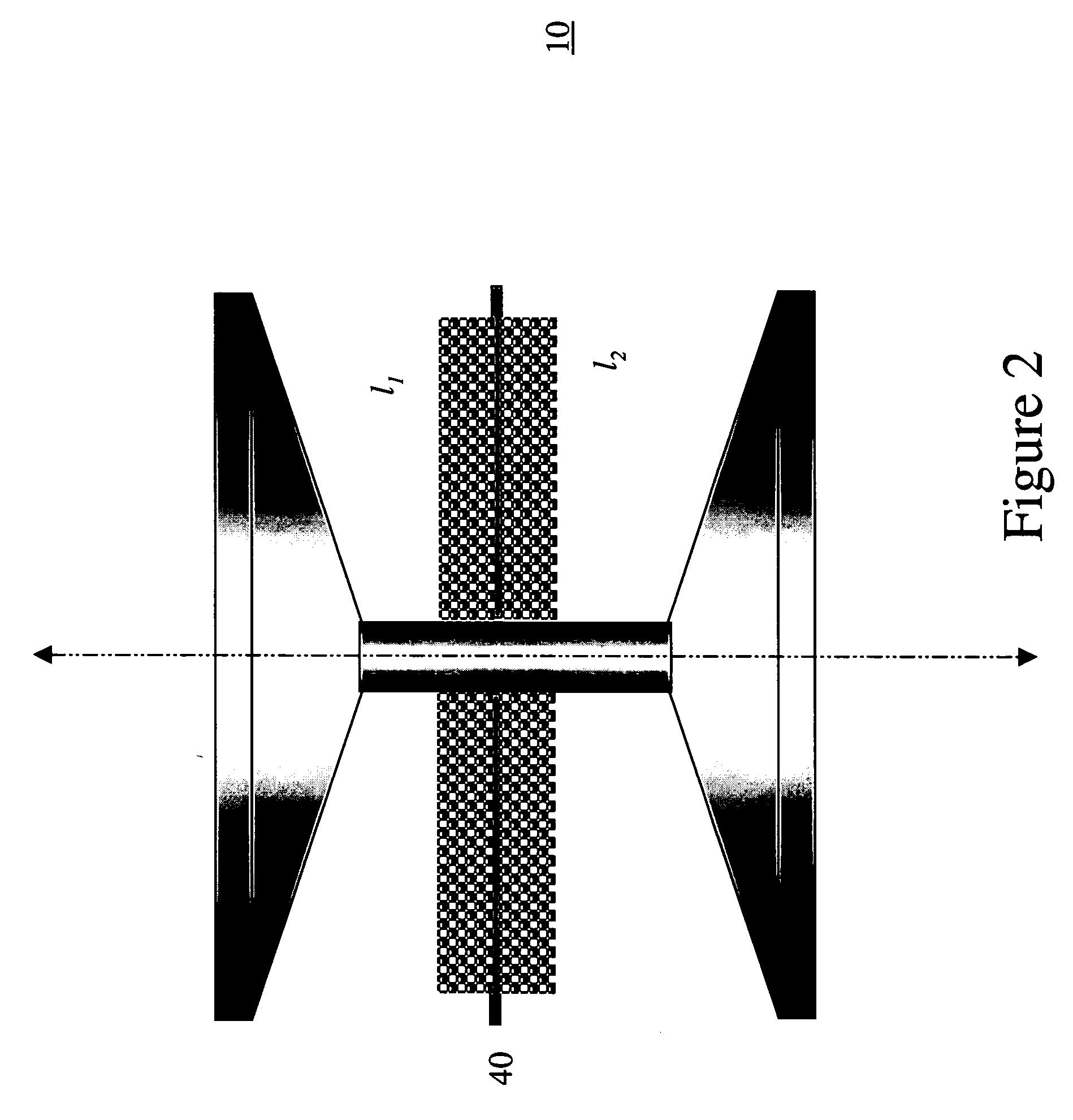
[0028]FIG. 2 is a diagram of a fiber optic accelerometer 10. Fiber coils l1, l2 are attached to opposite sides of a flexural disc 40, which may be supported by either the edges or the center (as shown in FIG. 2). When the transducer is subjected to upwards acceleration, the fiber coil l1 attached to the top of the disc is extended, while the coil l2 at the bottom of the disc is compressed. This generates a path imbalance between the arms of the interferometer to provide the phase shift for detection.

[0029] Fiber Selection ...


PUM


Abstract

A method of making a fiber optic accelerometer includes (a) drawing an optical fiber through a resin; (b) winding the resin coated fiber onto a disc mounted on an assembly having a central shaft; and (c) curing the resin-coated fiber. The optical fiber may be drawn through a resin by providing a container filled with a resin having an orifice therethrough and drawing the fiber through the orifice. The resin may be cured such that the fiber is bonded to the disc by curing the resin to the fiber and the disc at the same time.

Description

[0001] The present patent application claims priority to U.S. Provisional Patent Application No. 60 / 470,159, filed May 13, 2003, incorporated by reference herein in its entirety.[0002] The United States Government has certain rights to this invention pursuant to Contract No. NCRADA-NRL-00-273 between the United States Government (Department of the Navy) and Schlumberger Technology Corporation.FIELD OF THE INVENTION [0003] The present invention relates to optical fiber accelerometers suitable for high temperature applications and methods of manufacturing the same. BACKGROUND OF THE INVENTION [0004] Measurements of the earth's gravitational acceleration, and measurements of differences in the earth's gravitational acceleration between different depths in the earth, can be useful in determining the bulk density (or specific gravity) of various earth formations, among other applications. More particularly, measurements of gravity difference between two positions or depths may be used to...

Claims


Application Information

Patent Timeline
IPC IPC(8): G01P15/093G02B6/14
CPCG02B6/14G01P15/093
Inventor SHAH, JAGDISHRAMOS, ROGERIO T.SINDT, OLIVIERDRYDEN, PHILIPEVANS, CLIFFDALTON, MARK
Owner SCHLUMBERGER TECH CORP
Why Eureka
Try Eureka