
Adjustable tree stand

Active Publication Date: 2011-08-11
TONG PAI
View PDF3 Cites 8 Cited by
  • Summary
  • Abstract
  • Description
  • Claims
  • Application Information

AI Technical Summary

Benefits of technology

[0009]An object of the present invention is to provide an adjustable tree stand that facilitates manufacturing.
[0010]Another object of the present invention is to provide a highly safe adjustable tree stand.
[0011]Yet another object of the present invention is to provide an adjustable tree stand with parts that are less likely to be lost.
[0013]The adjustable tree stand also includes a control unit including a threaded rod mounted non-rotatably to the first mounting structure, and a slide seat connected to the first attachment member of the cable unit and coupled movably to the first mounting structure for sliding movement therealong. The control unit also includes a gear set mounted rotatably to the slide seat and threadedly engaging the threaded rod, and a drive part for driving rotation of the gear set to thereby cause the slide seat to move along the first mounting structure for adjusting a tension of the cable unit.
[0014]The invention therefore provides an adjustable tree stand with a fixed threaded rod that facilitates manufacturing and enhances safety.

Problems solved by technology

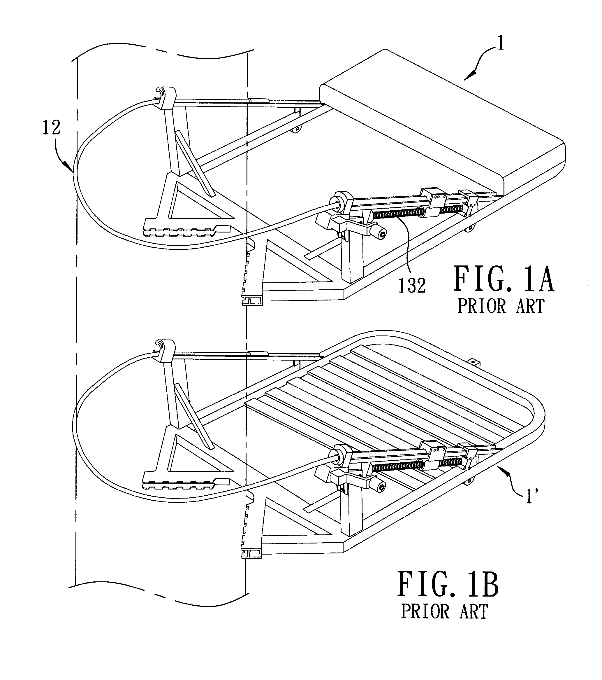
The conventional tree stand 1 may have a high defect rate.
These requirements may increase manufacturing complexity, labor costs, and a potential defect rate due to misaligned or improperly disposed components.
The conventional tree stand 1 may include a risk of structural failure.
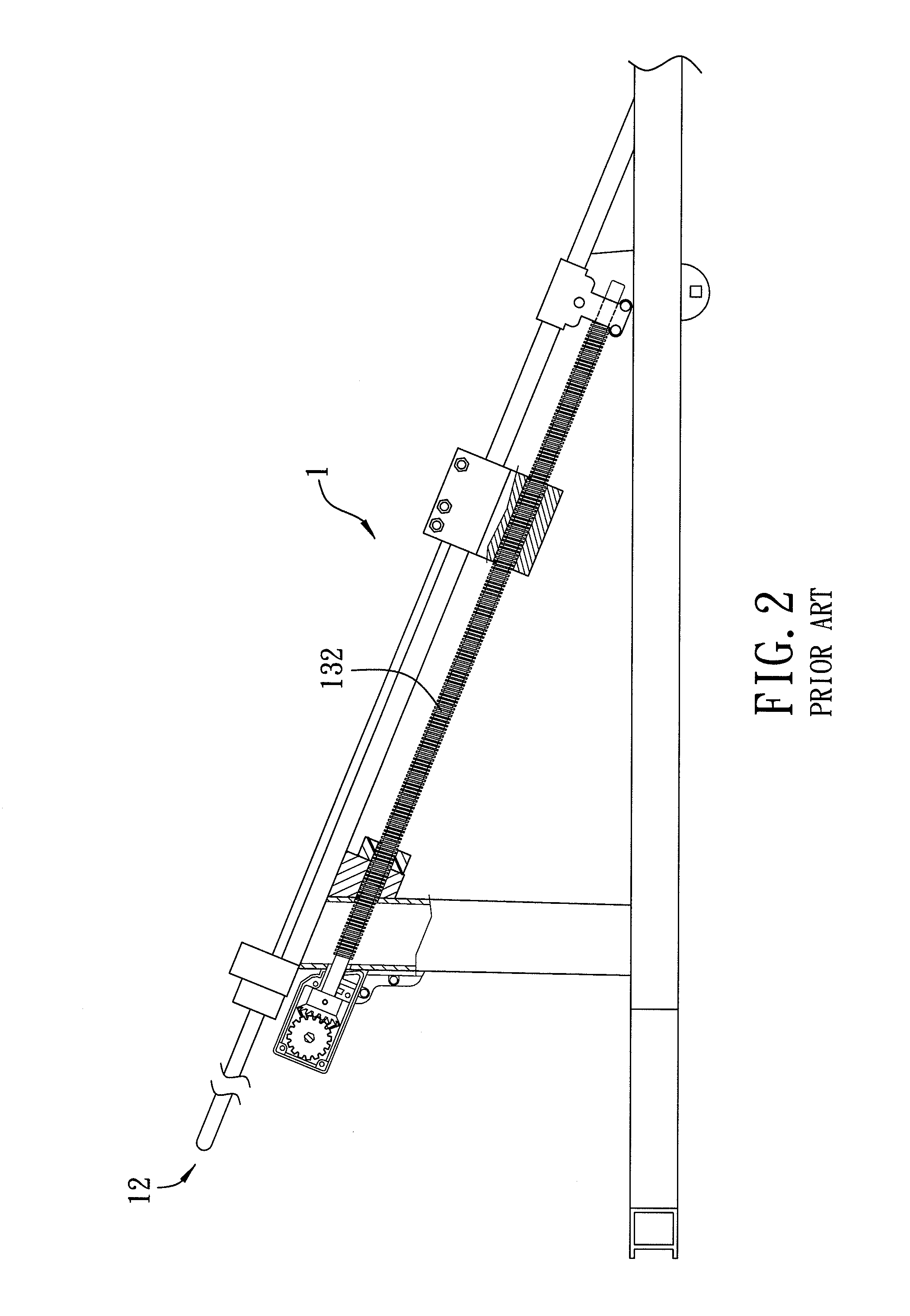
Damage or misassemble of the driving component of the conventional tree stand 1 may therefore allow the rotatable threaded rod 132 to be released, causing the conventional tree stand 1 to fail while supporting a user.
The conventional tree stand 1 may include a risk of loss of components.

Method used


Image

  • Adjustable tree stand
  • Adjustable tree stand
  • Adjustable tree stand

Examples


Embodiment Construction

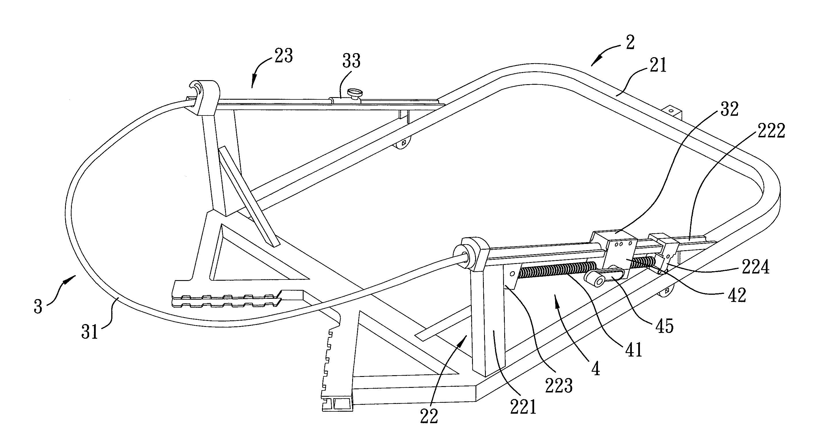
[0022]Referring to FIGS. 4, 5 and 6, a pair of adjustable tree stands according to the preferred embodiment of the present invention may be hung from a tree and vertically separated. The adjustable tree stand includes a support unit 2, a cable unit 3 and a control unit 4.

[0023]The support unit 2 includes a support platform 21 adapted for providing support for standing or sitting, and a first mounting structure 22 and a second mounting structure 23 mounted on opposite lateral sides (e.g., lateral parts) of the support platform 21, respectively. The first mounting structure 22 includes a strut 221 that extends upward from a forward section of a corresponding one of the lateral parts, and a guide 222 that extends rearward and inclines downward from a top part of the strut 221. The first mounting structure 22 further includes a front block 223 mounted to the strut 221 and formed with a blind hole 225 that opens rearward, and a rear block 224 fixed to a rearward part of the guide 222.

[00...


PUM


Abstract

An adjustable tree stand includes a support unit that includes a support platform having two lateral parts, and that further includes first and second mounting structures, each mounted to a corresponding one of the lateral parts of the support platform. The adjustable tree stand further includes a cable unit that includes a cable, a first attachment member connected to one end of the cable, and a second attachment member connected to the other end of the cable for releasably coupling with the second mounting structure.The adjustable tree stand also includes a control unit including a threaded rod mounted non-rotatably to the first mounting structure, and a slide seat connected to the first attachment member of the cable unit and coupled movably to the first mounting structure for sliding movement therealong.

Description

CROSS REFERENCE TO RELATED APPLICATION[0001]This application claims priority to Taiwanese application no. 099202804 filed on Feb. 10, 2010, which is herein incorporated by reference.BACKGROUND OF THE INVENTION[0002]1. Field of the Invention[0003]The invention relates to a tree stand, more particularly to an adjustable tree stand that adjusts tension of a cable by moving an operable part.[0004]2. Description of the Related Art[0005]Referring to FIGS. 1A, 1B, 2 and 3, and to U.S. Pat. No. 7,287,623, a conventional tree stand may be attached to a tree by a cable 12. In FIGS. 1A and 1B, tree stands 1 and 1′ differ primarily in whether they provide support for standing or sitting. Accordingly, tree stands 1 and 1′ are not separately discussed below. The conventional tree stand 1 includes a rotatable threaded rod 132, which is used to tighten the cable 12 around a tree.[0006]The conventional tree stand 1 may have a high defect rate. The rotatable threaded rod 132 of the conventional tree ...

Claims


Application Information

Patent Timeline
IPC IPC(8): E04G5/00F16H25/20
CPCY10T74/18752A63B27/00
Inventor TONG, PAI
Owner TONG PAI
Learn More