
Apparatus and method for curing materials with light radiation

a technology of radiation curing and apparatus, applied in dental surgery, instruments, dental tools, etc., can solve the problems of inability to filter harmful wavelengths of blue light, inability to accurately detect harmful wavelengths of light, and inability to detect harmful wavelengths, etc., to achieve efficient and efficient transmission and collimation of light

Inactive Publication Date: 2005-01-06
THE KERR
View PDF99 Cites 58 Cited by
  • Summary
  • Abstract
  • Description
  • Claims
  • Application Information

AI Technical Summary

Benefits of technology

"The present invention is a curing instrument for light-curable compounds, such as dental compounds, that uses a plurality of solid state, light-emitting elements. These elements are mounted on a substrate and form a collective array that emits light within a narrow band of wavelengths, specifically the blue wavelength. The instrument is designed to be portable and handheld, with a housing that supports the array and a power supply. The optical focusing device is a non-imaging optic that efficiently collimates and directs the light emitted from the array onto a work surface, such as a tooth. The array is positioned at the distal end of the housing for direct delivery to the work surface. The instrument is designed to be disposable and discarded after each use, eliminating the need for autoclaving. The non-imaging optic and reflective element are coupled to the end of the disposable sleeve for efficient collimation and direction of light. The array emits light within a range of 0-180°, and the non-imaging optic is positioned to capture the light within the 180° range and effectively collimate it into a beam directed to the work surface. The instrument may use a single non-imaging optic or multiple non-imaging optics."

Problems solved by technology

First, it is known that certain wavelengths of blue light are harmful to human tissue.
While attempts are made to direct the light beam only on to the tooth surface, a certain amount of oral tissue exposure to the light is inevitable.
Therefore, harmful wavelengths must be filtered.
As a result, dental curing lights must utilize special and complicated filtering devices or filters which receive the broad spectrum light from the lamp element, and then filter the light to provide only the light at the desirable wavelengths.
Therefore, prior art curing techniques and light devices have generally been very inefficient, because a large amount of the radiated light power is lost simply due to filtering of a significant part of the light spectrum.
Additionally, the efficiency of the prior art dental curing lights is further degraded by power losses due to the angle of incidence of the radiated light upon the filtering element.
This further decreases the amount of desirable light power which is available for curing the dental compound.
Conversely, a higher amount of light at undesirable wavelengths may also be reflected onto the tooth surface, rather than being transmitted through the filtering element to be dissipated.
Still another drawback with prior art curing lights is that they generate significant amounts of heat and therefore require complicated cooling systems to operate within the proper temperature range.
The high power output required for the halogen bulb to produce the desired light power level for curing, creates a significantly high thermal load on the shields.
The additional cooling elements increase the size of the light device and complicate its design.
The absorption devices and heat dissipating systems not only complicate the operation and design of the light device, but also make it more expensive to produce, and more subject to operational failure.
Another drawback of prior art dental curing light devices is the limited operational life of the lamp element, such as a halogen bulb.
The bulbs frequently burn out and must be replaced.
Furthermore, the heat generated inside the light device, which is usually enclosed, shortens the effective operational lifespan of the bulb.
While specific blue light is provided by the LEDs without significant filtering, various of these devices require complicated internal designs for focusing of the curing light, or require specific electronic control of the LEDs.
Furthermore, large numbers of conventional LEDs are necessary.
Therefore, it has been difficult to provide a suitable curing light using conventional LEDs, which will generate sufficient curing power in a small incomplete design.
Using traditional packaged LEDs, as disclosed in the above-cited art, has specifically presented difficulties associated with generating sufficient curing power within a reasonably sized device which may be adequately cooled.
Further complications with such devices have resulted from attempts to concentrate the light from the large grouping of traditional LEDs into a small area and at a sufficient power density so as to be useful for curing.
Such difficulties in providing a suitable curing light device utilizing the existing traditional packaged LED technology is highlighted by the lack of a well-received and widely-utilized dental curing light on the market which utilizes such technology.
Still another drawback associated with prior art curing lights is their inefficiency in transmitting the light to the work surface, such as a tooth surface, once the light has been generated by the element or bulb.
The air / glass interfaces between the generating elements and the input end of the light guide and the output end of the light guide and the inside of the mouth are inefficient and may produce approximately a 10% loss in power per interface.
Such inefficiencies further increase the cure time that is necessary, and / or create the need for higher power (and associated heat) to provide the necessary curing light intensity.
Furthermore, the high heat required for sterilization may, over time, damage components of the curing light.

Method used


Image

  • Apparatus and method for curing materials with light radiation
  • Apparatus and method for curing materials with light radiation
  • Apparatus and method for curing materials with light radiation

Examples


Embodiment Construction

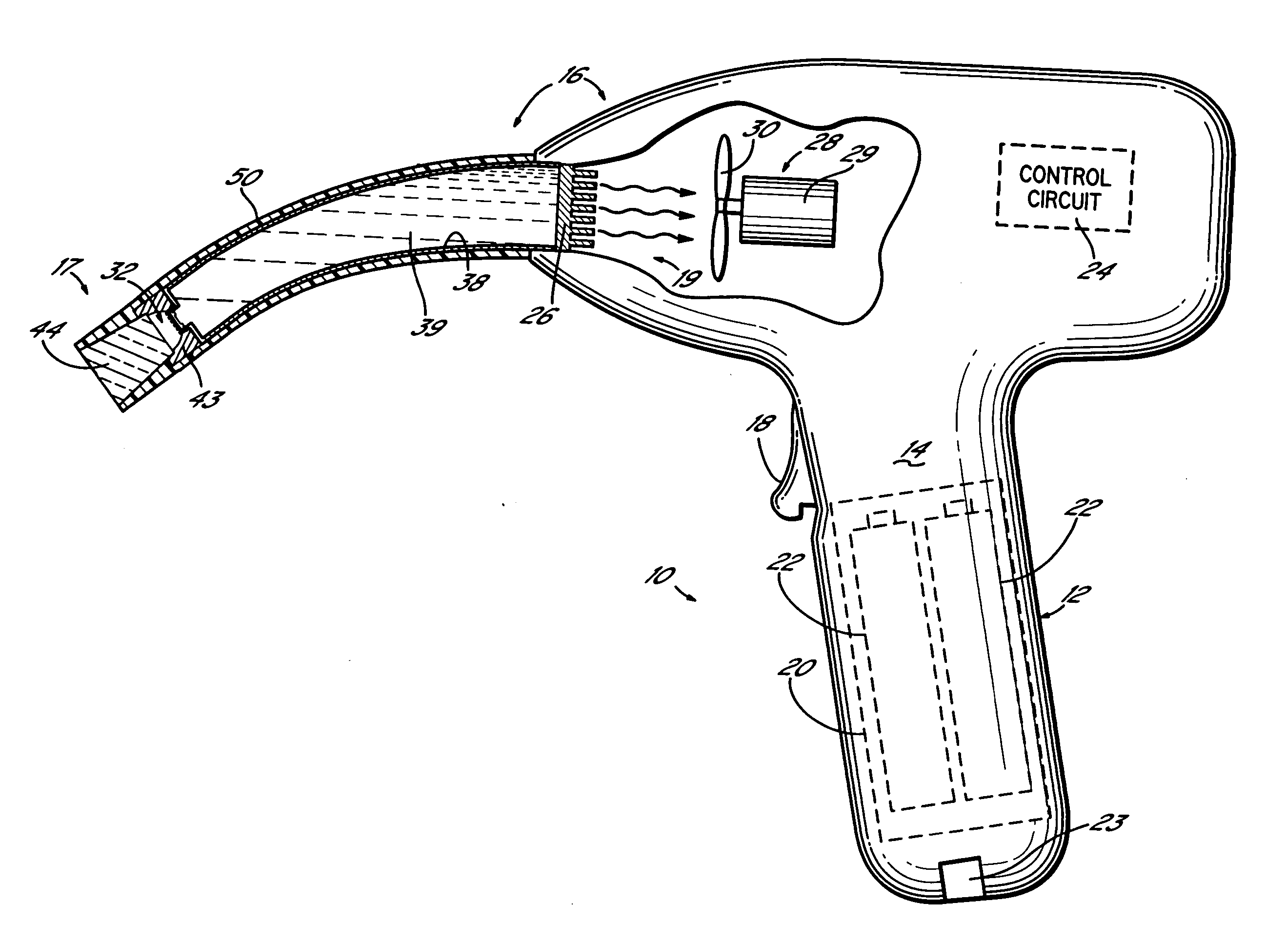
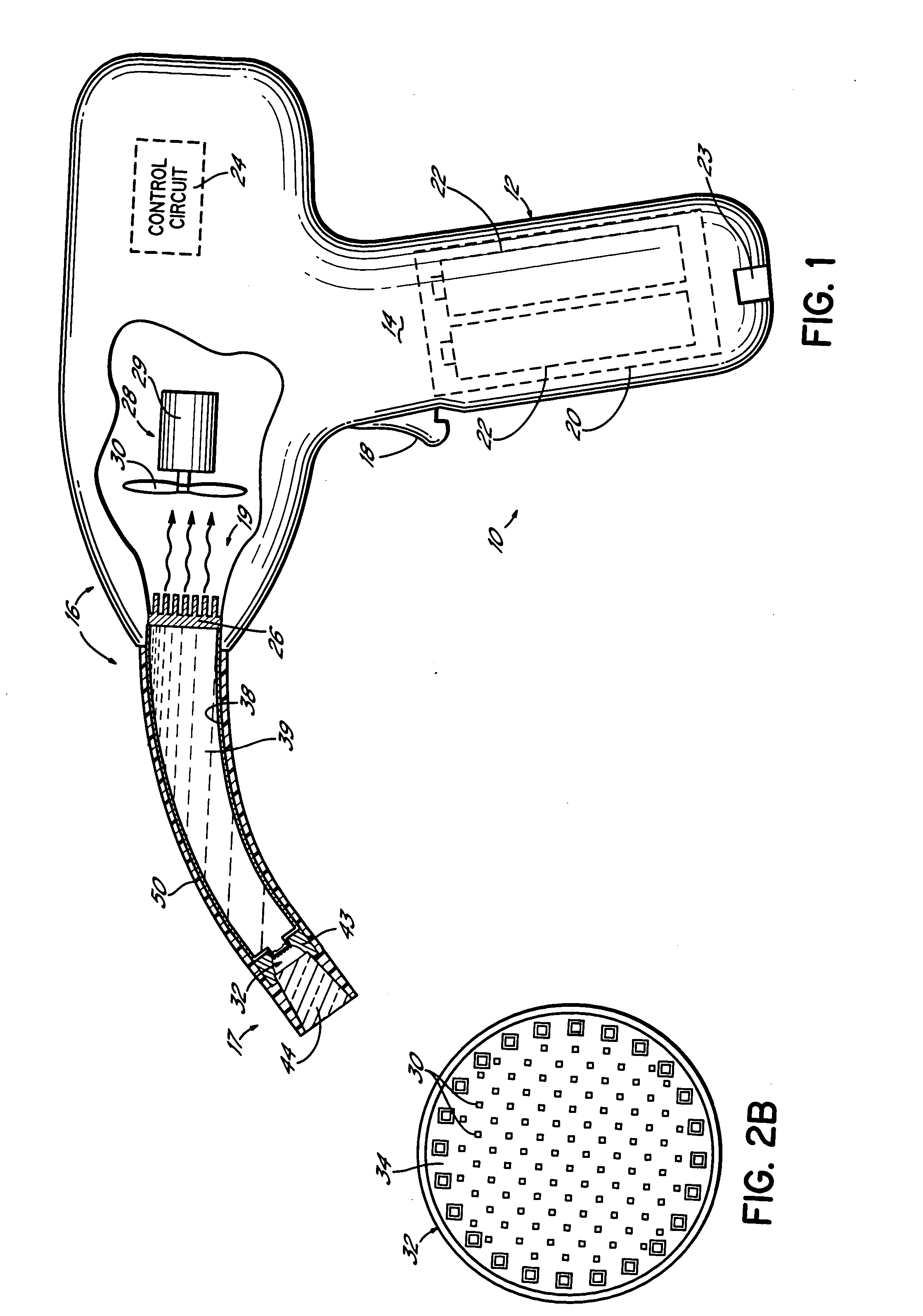
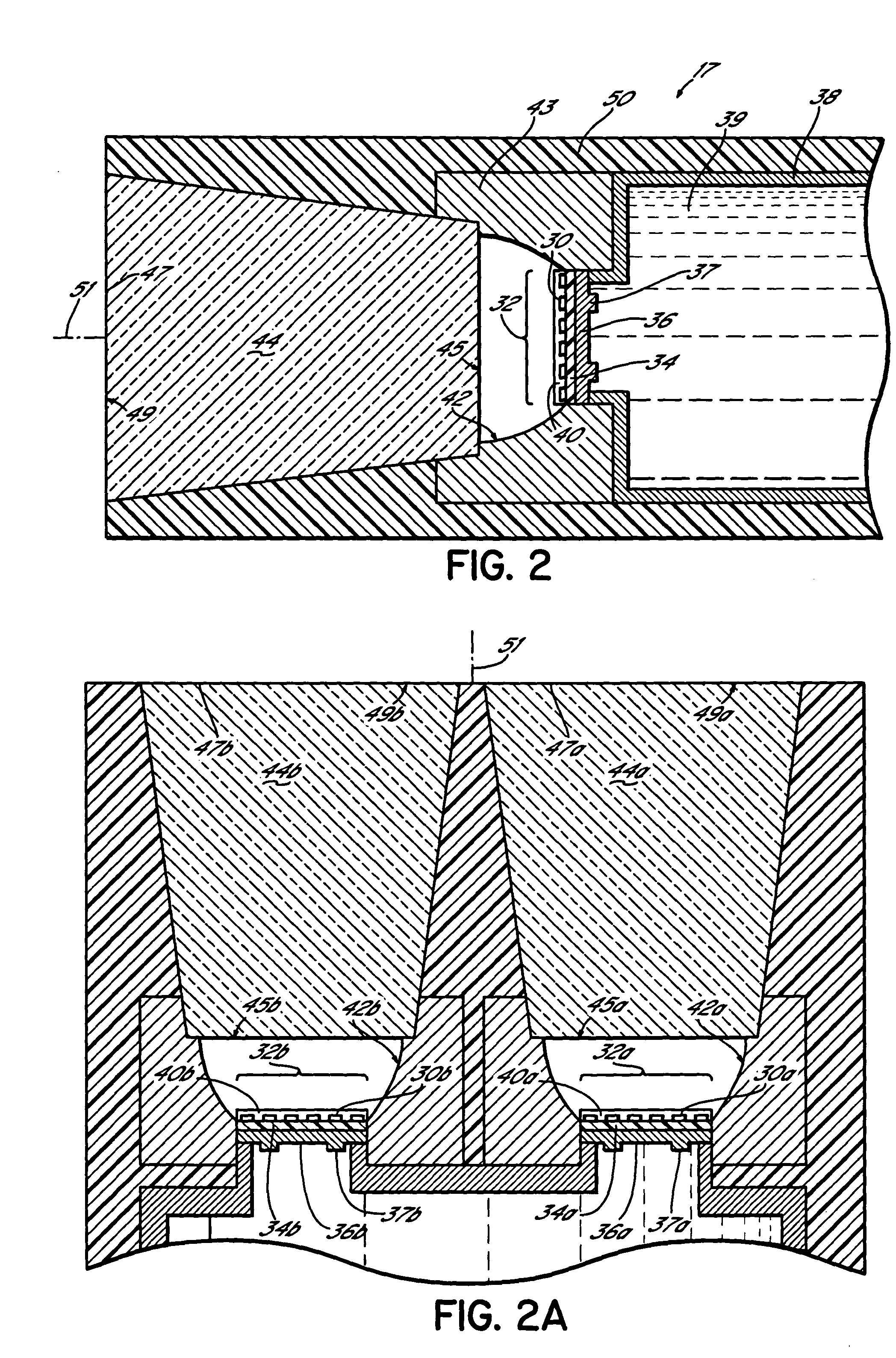
[0041]FIG. 1 illustrates one embodiment of a curing light device or curing light for curing light-curable compounds such as dental compounds in accordance with the aspects of the present invention. In FIG. 1, device 10 includes a housing 12 which is to be manipulated for curing. Housing 12 is generally gun-shaped and includes a handle portion 14 and a barrel portion 16. The operator, such as a dentist, grips housing 12 around the handle portion 14 and directs the barrel portion 16 in the direction of the tooth surface (or other work surface) and compound to be cured (not shown). For curing dental filling and coating compounds, the dentist would generally position at least part of the barrel portion in the mouth of a patient with a radiating end 17 of the barrel portion pointing at a particular tooth or teeth. The handle portion 14 includes an operational trigger switch 18 which is operably coupled to a power supply 20 and / or control circuit 24 for selectively operating the device an...


PUM

PropertyMeasurementUnit
acceptance angleaaaaaaaaaa
output poweraaaaaaaaaa

Abstract

An instrument and method for curing light-curable compounds in the mouth of a patient, the instrument comprising a housing and a plurality of solid state, light-emitting elements on a substrate supported by the housing. The elements form a collective array on the substrate operable for collectively emitting light having wavelengths within a narrow band of wavelengths. An optical focusing device is positioned to intercept the light emitted by the array of elements and includes a non-imaging optical device which is operable for collimating the light from the array into a beam to be directed onto a compound for curing the compound. A disposable sleeve covers the housing and array and may incorporate the optical focusing device. The sleeve is removed and discarded after use to eliminate the need to autoclave the instrument.

Description

RELATED APPLICATIONS [0001] This application is a continuation of U.S. Ser. No. 09 / 632,260, filed on Aug. 4, 2000 and entitled “Apparatus and Method for Curing Materials with Light Radiation,” which, in turn, is a continuation-in-part of U.S. Pat. No. 6,200,134, filed on Jan. 20, 1998 and issued on Mar. 13, 2001, which application and patent are incorporated herein by reference in their entireties.FIELD OF THE INVENTION [0002] This application is related to the curing of materials with radiation and, more specifically, to curing dental coating and filling compounds with light. BACKGROUND OF THE INVENTION [0003] Curable adhesive compounds and bonding or filling compounds are widely used for structurally connecting object surfaces together or for filling gaps, openings and cavities in an object surface. Such curable compounds are generally manipulated and positioned on the object surface in a semi-solid state and are then hardened or cured in position to a more solid and permanent sta...

Claims


Application Information

Patent Timeline
Patent Type & Authority Applications(United States)
IPC IPC(8): A61C13/15A61N5/06B29C35/08G02B6/42
CPCA61C19/004A61N2005/0652Y10S362/80B29C2035/0833G02B6/4298B29C35/08A61C2204/002
Inventor LOGAN, JOSEPH N.KNOX, RAYMOND L.
Owner THE KERR
Learn More