
Apparatus and process for the lateral deflection and separation of flowing particles by a static array of optical tweezers

a static array and particle technology, applied in the field of system and method for achieving particle fractionation, can solve the problems of requiring system flushing and restarting, affecting the efficiency of the system, and a number of limitations of the techniqu

Inactive Publication Date: 2005-01-06
UNIVERSITY OF CHICAGO
View PDF10 Cites 13 Cited by
  • Summary
  • Abstract
  • Description
  • Claims
  • Application Information

AI Technical Summary

Benefits of technology

[0006] It is therefore an object of the invention to provide an improved system and method for the lateral deflection of flowing particles that is both tunable and continuous.
[0007] It is another object of the invention to provide an improved system and method for laterally deflecting particles that does not become readily clogged with particles.

Problems solved by technology

Although moderately effective, this technique includes a number of limitations.
Furthermore, such lattices tend to suffer from clogging, requiring flushing of the system and restarting.

Method used


Image

  • Apparatus and process for the lateral deflection and separation of flowing particles by a static array of optical tweezers
  • Apparatus and process for the lateral deflection and separation of flowing particles by a static array of optical tweezers
  • Apparatus and process for the lateral deflection and separation of flowing particles by a static array of optical tweezers

Examples


example

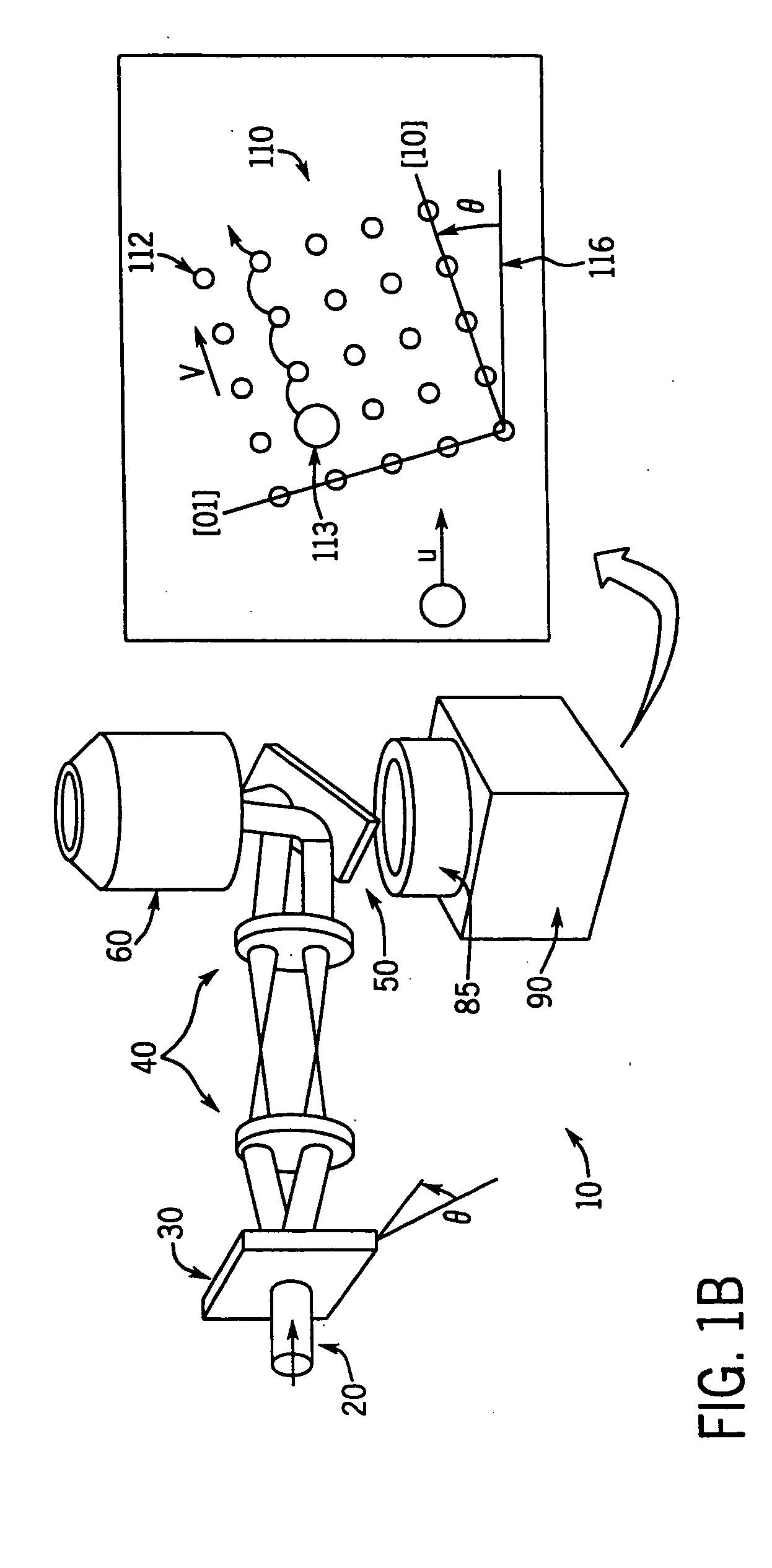
[0043] One preferred system, shown schematically in FIG. 1 includes 1.5 μm diameter silica spheres (Bangs Labs) dispersed in deionized water and confined to a horizontal layer 15 μm thick between parallel glass surfaces. These spheres are considerably denser than water and readily sediment into a monolayer about 2 μm above the lower wall of the sample container. The edges of the sample volume are sealed to form a flow channel. Two glass tubes bonded to holes through the upper glass wall provide access to the sample volume and serve as reservoirs for colloid, water and clean mixed-bed ion exchange resin. The ends of the tubes are connected to continuous flows of humidified Ar gas. Blocking one of the flows causes a pressure imbalance which drives colloid through the sample chamber and past the 75×58 μm2 field of view of a 100×NA 1.4 oil-immersion objective mounted on an Olympus IMT-2 microscope base. By controlling the flow of Ar, we can induce colloid to travel at up to 100 μm / sec o...


PUM

PropertyMeasurementUnit
tilt angleaaaaaaaaaa

Abstract

A method and apparatus for laterally deflecting and / or separating a flow of particles using a static array of optical tweezers. In an array of optical tweezers with a lattice constant larger than the size of a particle of interest, particles driven past the array by an external force experience an additional interaction with the array of traps. By altering the angle of the array of traps relative to the external force, the particles' movement from trap to trap inside the array can be biased away from the direction of the external force, thereby enabling selective deflection and / or separation of particles.

Description

CROSS-REFERENCE TO RELATED PATENT APPLICATIONS [0001] This application is a Continuation of U.S. application Ser. No. 09 / 951,117, filed Sep. 13, 2001, incorporated herein by reference in its entirety.[0002] This invention was made with U.S. Government support under Grant No. DMR-9730189 awarded by the National Science Foundation and through the MRSEC Program of the National Science Foundation under Grant Number DMR-9880595. The Government has certain rights in this invention.FIELD OF THE INVENTION [0003] The present invention relates generally to a system and method for achieving a fractionation of particles. More particularly, the present invention relates to a system and method for achieving a lateral fractionation and / or separation of particles through the use of a static array of optical traps BACKGROUND OF THE INVENTION [0004] A number of techniques are conventionally known that are capable of fractionating particles in limited circumstances. For example, one such technique inv...

Claims


Application Information

Patent Timeline
Patent Type & Authority Applications(United States)
IPC IPC(8): B82B3/00G01N15/14G01N30/00G02B21/32G01N30/02G21K1/00
CPCG01N30/00G01N30/02G01N2015/149G03H2001/0077B01D2015/3895G01N15/149
Inventor GRIER, DAVID G.KORDA, PAMELA T.
Owner UNIVERSITY OF CHICAGO
Learn More