Fault detection system and method
- Summary
- Abstract
- Description
- Claims
- Application Information
AI Technical Summary
Benefits of technology
Problems solved by technology
Method used
Image

Examples
Embodiment Construction
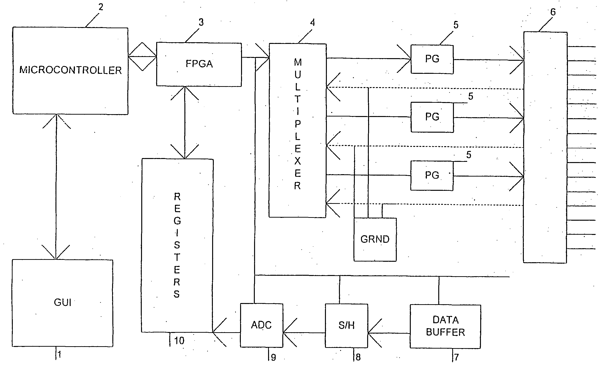
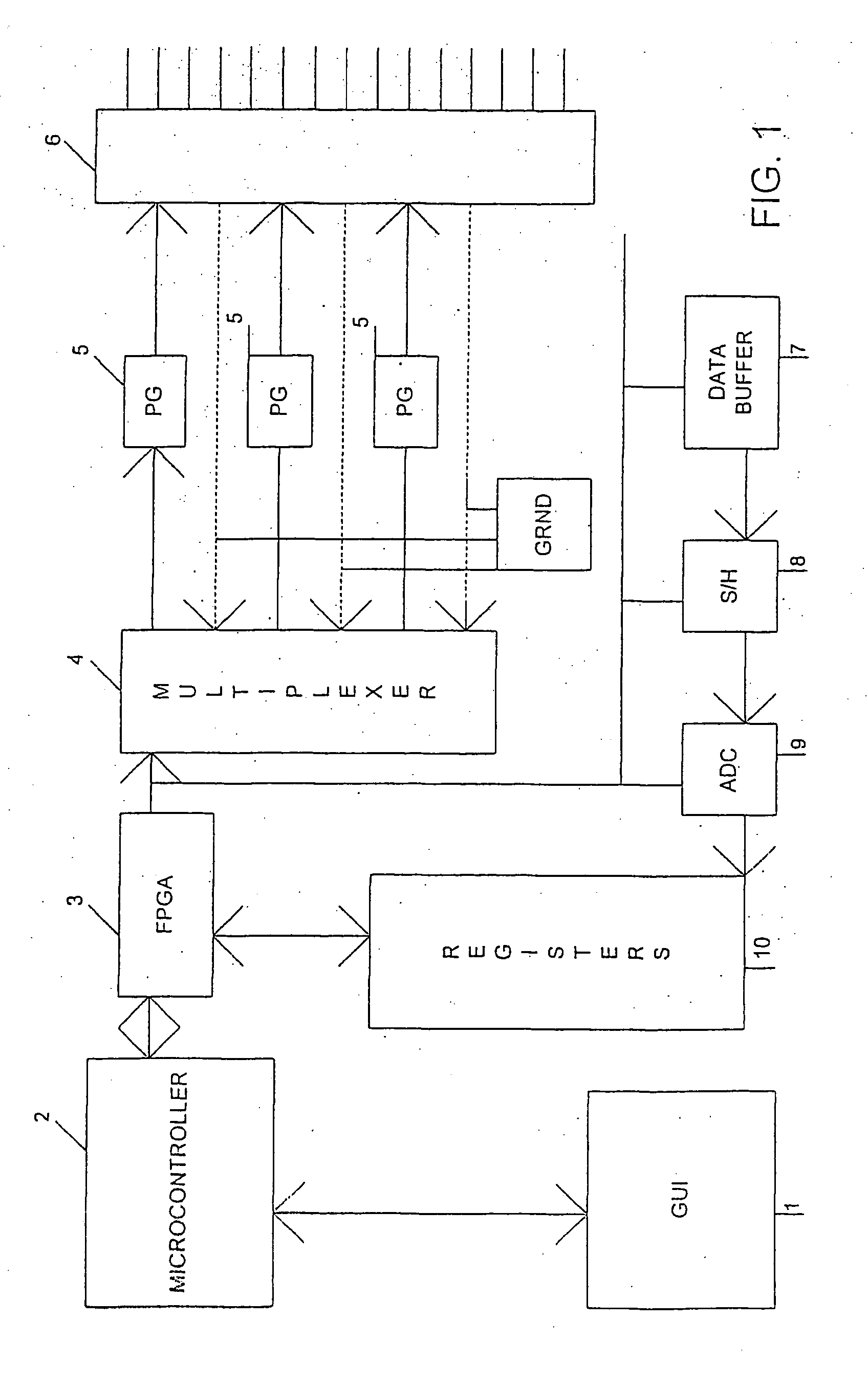
[0027] FIG. 1 is a block diagram of a time domain reflectometry system according to an embodiment of the present invention. A graphic user interface (GUI) 1 is provided on a terminal, user input device, computer or the like for interacting with the system. Inputs via the GUI 1 are passed to a micro-controller 2. The microcontroller is in communication with a fixed programmable gate array (FPGA) 3 for controlling operation of the time domain reflectometry system. The FPGA 3 is connected to a multiplexer 4 for sending and receiving signals to and from one or more of a number of transmission mediums under test. Under control of the multiplexer 4, a transmitter, such as a variable pulse generator (PG) 5 produces interrogating energy pulses that are launched into its respective connected transmission medium to be tested via a test port 6. The transmission medium may be shielded or unshielded twisted pairs, coaxial cables, single core cabling or other types of metallic transmission medium...
PUM
 Abstract
Description
Claims
Application Information
 - R&D
- Intellectual Property
- Life Sciences
- Materials
- Tech Scout
- Unparalleled Data Quality
- Higher Quality Content
- 60% Fewer Hallucinations
Browse by: Latest US Patents, China's latest patents, Technical Efficacy Thesaurus, Application Domain, Technology Topic, Popular Technical Reports.
© 2025 PatSnap. All rights reserved.Legal|Privacy policy|Modern Slavery Act Transparency Statement|Sitemap|About US| Contact US: help@patsnap.com