Organic light emitting devices

a light-emitting device and organic technology, applied in the direction of discharge tube luminescnet screen, other domestic articles, natural mineral layered products, etc., can solve the problems of unstable efficiency and instability of single-mixed-layer organic light-emitting devices, the operation life of organic light-emitting devices described above is relatively short, and the efficiency of known devices is generally less than conventional devices, etc., to achieve the effect of minimizing power consumption, increasing power conversion efficiency, and improving efficiency

Active Publication Date: 2004-10-21
LG DISPLAY CO LTD
View PDF6 Cites 65 Cited by
  • Summary
  • Abstract
  • Description
  • Claims
  • Application Information

AI Technical Summary

Benefits of technology

0013] This invention overcomes the above-described disadvantages of known organic light emitting devices (OLEDs) and provides improved organic light emitting devices having enhanced efficiency and operational lifetimes. In addition, the organic light emitting devices according to this invention provide operational stability with minimized power consumption and increased power conversion efficiency.

Problems solved by technology

However, such single mixed layer organic light emiting devices are generally less efficient an unstable compared to multilayer organic light emitting devices.
However, such known devices have been found to be generally less efficient than conventional devices including separate layers of hole transport material and emitting electron transport material.
To date, organic light emitting devices as described above have relatively short operational lifetimes before their luminance drops to some percentage of its initial value.
Methods of providing interface layers and doping have been developed to increase the operational lifetime of organic light emitting devices to several tens of thousands of hours for room temperature operation, however, the effectiveness of the known organic light emitting devices deteriorates dramatically for high temperature device operation, as the existing methods used to extend the device lifetimes lose their effectiveness at higher temperatures.
However, these devices usually require excessive excitation voltages on the order of 100 volts or greater.
While recent progress in organic EL research has elevated the potential of organic EL devices for widespread applications, the performance levels of current available devices may still be below expectations.
These electron transport materials may be suitable for use in EL devices with light emission in green or longer wavelength region, however, for blue-emitting EL devices they are of limited use.
Although prior art electron transport materials may fluoresce in the blue region, the performance characteristics of the resulting EL devices still possess many disadvantages such as poor operation stability.

Method used


Image

  • Organic light emitting devices
  • Organic light emitting devices
  • Organic light emitting devices

Examples


example ii

Fabrication of Organic EL Devices of the Invention

[0095] Device A: A 500 .ANG. indium tin oxide (ITO) anode coated glass substrate was selected, the thickness of the glass substrate being about 1 millimeter. The glass was cleaned with a commercial detergent, rinsed with deionized water and dried in a vacuum oven at 60.degree. C. for 1 hour. Immediately before use, the glass was treated with UV ozone for about 0.5 hours.

[0096] The ITO anode coated on the glass substrate was then placed in a vacuum deposition chamber and a hole injection and transporting zone was applied. The zone deposition rate and thickness were controlled by an Inficon Model IC / 5 controller. Under a pressure of about 5.times.10.sup.-6 Torr, a 20 nanometers thick buffer was deposited on the ITO glass substrate through the evaporation of N,N'-1-naphthyl-N,N'-diphe-nyl-1,1'-biphenyl-4,4'-diamine at a rate of 0.6 nanometer / second from a tantalum boat.

[0097] Onto the hole injection and transporting zone was deposited a...


PUM

PropertyMeasurementUnit
excitation voltagesaaaaaaaaaa
thicknessaaaaaaaaaa
thicknessaaaaaaaaaa

Abstract

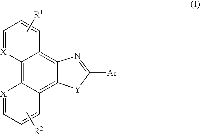
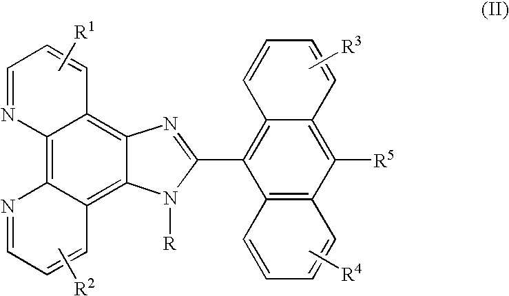
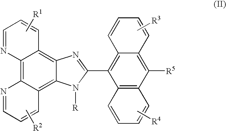
The present invention is an organic light emitting device (OLED) comprising an anode, a cathode and a luminescent region provided between the anode and the cathode. The luminescent region comprises an electron injection and transporting zone and at least one of a hole injection and transporting zone and a mixed charge transport layer. One or both of the electron injection and transporting zone and the mixed charge transporting layer comprises an azole compound represented by formula I and/or II. The provision of the novel azole compounds of the invention as electron transport materials within an organic electroluminescent device advantageously reduces power consumption and increases power conversion efficiency within the device and as such, are suitable for a variety of display applications.

Description

[0001] This application claims the benefit of U.S. Provisional Application No. 60 / 463,312, filed Apr. 17, 2003, the disclosure of which is totally incorporated herein by reference.[0002] Organic light emitting devices (OLEDs) are useful for display applications and in particular, mobile hand held display applications. To achieve efficient electroluminescence OLEDs have typically been manufactured to include separate layers of a hole transport material (HTM) and an emitting electron transport material (ETM). During operation, an applied electric field causes positive charges (holes) and negative charges (electrons) to be respectively injected from the anode and the cathode of the OLED to recombine and thus produce light emission. In other known OLED displays, the hole transport and electron transport layers are doped with organic dyes in order to enhance the efficiency or to improve the stability of the OLED. OLEDs have also been developed in which hole transport material and emittin...

Claims


Application Information

Patent Timeline
Patent Type & Authority Applications(United States)
IPC IPC(8): C07D471/14H01L51/00H01L51/50H05B33/26
CPCC07D471/14H01L51/0052H01L51/0058H01L51/0072H01L51/0081H01L51/5048H01L2251/308H05B33/26Y10S428/917Y02E10/549H10K85/626H10K85/615H10K85/6572H10K85/324H10K50/14H10K2102/103
Inventor AZIZ, HANYVAMVOUNIS, GEORGEHU, NAN-XINGPOPOVIC, ZORAN D.COGGAN, JENNIFER A.
Owner LG DISPLAY CO LTD
Why Eureka
Try Eureka